KAMAZ car winch
The winch is designed for self-pulling and pulling cars and trailers through difficult areas
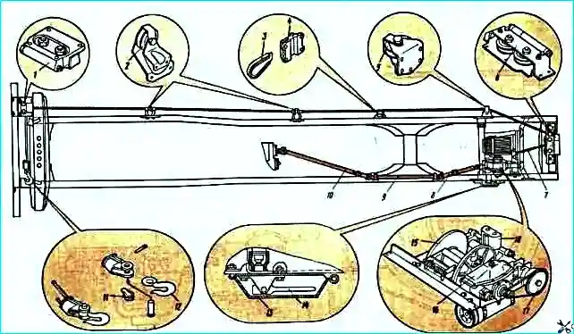
It consists of a drive, a worm gearbox, a drum with a cable attached to it, a band brake and a cable guide.
The winch is used only on KamAZ-4310 vehicles; the winch cable can be extended both forward and backward.
Working length of the cable when extending backwards is 86 m,
- - when dispensing forward - 79 m;
- - maximum traction force when extending the cable backwards 77 kN,
- - when extending forward - 54 kN,
- - using a block - 154 and 108 kN, respectively.
The winch is installed at the rear of the frame on two crossbars.
The winch is driven by a single-speed power take-off mounted on the transfer case.
The output shaft of the box is installed in the bearing housing on two ball bearings.
A flange with a reflector is attached to the splines of the output shaft for connecting the drive shaft of the winch drive.
A movable power take-off clutch moves along the splines of the front end of the output shaft, which engages with the splines of the transfer case drive shaft.
The bearing cup is closed with a lid sealed with a gasket. To prevent oil from leaking out, a rubber cuff with a spring is installed in the lid of the glass.
The power take-off is activated by a membrane-type pneumatic mechanism with remote control.
The torque of the power take-off is transmitted to the gearbox by three cardan shafts 8, 9, 10 (Fig. 1).
There is a shear safety bolt on the rear propeller shaft to protect parts from overload.
The front driveshaft has a movable spline connection, which compensates for installation inaccuracies.
The intermediate cardan shaft is mounted on two supports of the same design.
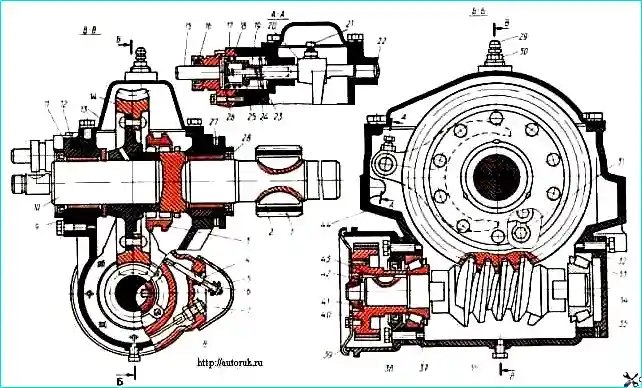
Winch gearbox: 1 - splined bushing; 2, 43 - keys; 3 - engagement clutch; 4, 23, 24 - springs; 5 - spring cover; 6, 7, 41 - nuts; 8 - brake band; 9, 42 - thrust washers; 10 - drum shaft; 11 - glass; 12, 18, 27, 35 - gaskets; 13 - crankcase cover; 14 - worm wheel; 15 - thrust pin of the rod; 16 - oil seal; 17 - rod cover; 19 - fork rod; 20 - power plug; 21 - set screw; 22 - plug; 25 - stem glass; 26 - cover; 28 - cuff; 29 - safety valve; 30 - adapter; 31 - bolt; 32 - rear bearing cover; 33, 37 - bearings; 34 - gear worm; 36 - plug; 38 - front bearing cover; 39 - drum reflector; 40 - brake drum; 44 - winch gear housing
The winch gearbox mechanism consists of a globoidal pair: a worm 34 and a worm wheel 14 with a gear ratio of 31.
The worm wheel 14 is attached to the hub, which is connected to the drum shaft 10 by a movable coupling 3. The drum is mounted on the shaft through splined sleeve 1 on key 2.
An automatic band brake is installed on the gearbox worm, designed to brake the gearbox worm shaft when the clutch is disengaged, as well as when the safety bolt of the propeller shaft fork is cut off in case of overload.
Drum 40 of the brake mechanism is installed at the end of the worm shaft.
The drum is braked by band 8 of the brake mechanism with friction linings.
One end of the tape is fixedly fixed with nuts 7 in the front bearing cover 38, and the other is movably fixed in the hole of the same cover through a spring 4, which tightens the tape in the direction opposite to the rotation of the worm shaft 34 when winding the winch cable onto the drum.
The tape compresses the spring under the influence of friction, which leads to a weakening of the pressure of the tape on the brake drum.
When the worm shaft rotates in reverse under the influence of friction, the band self-tightens and the drum is braked due to the rigid fastening of the second end of the brake band.
At low worm shaft rotation speed The braking force created by the automatic braking mechanism is insignificant and does not prevent the cable from unwinding.
If the safety bolt is cut off when the drum rotates at an increased frequency, the effect of the braking mechanism becomes significant and contributes to the self-braking of the worm gear.
The tension of the brake band is adjusted by tightening the spring.
When tightening nut 7, the braking torque increases.
The cable layer ensures uniform, dense laying of the cable on the drum.
The body 2 of the cable laying machine makes a reciprocating movement along the lead screw 13, laying the cable along the drum. Pipe 15, rigidly connected to the body, and the roller are guides.
The lead screw with left and right threads is mounted on a bearing 9 in the drive housing 10 and two supports inside the pipe, driven by a chain drive from the drum shaft through the drive and driven sprockets 7.
The cable is fixed to the winch drum and passes between two rollers 1 mounted on axles 5.
The stroke of the body is coordinated with the rotation of the drum so that for each revolution of the drum the cable handler body moves one step of the cable turn.
The winch is also equipped with a pressure roller with a spring located on top of the drum.
Winch cable 7 is secured to hook 12 with a wedge 11. This allows you to remove the hook by knocking out the wedge and pull the cable back.
A wedge 3 is installed on the right side member of the frame, which serves to secure the front end of the cable when pulling the car back using a block.
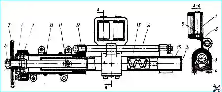
Cable laying machine: 1 - rollers; 2 - cable laying body; 3 - cracker cover; 4 - cracker; 5 - roller axis; 6 - nut; 7 - asterisk; 8 - housing cover; 9 - ball bearing; 10 - drive housing; 11 - oiler; 12 - sealing ring; 13 - lead screw; 14 - guide; 15 - pipe; 16 - plug
The winch drive is controlled remotely, electro-pneumatically, by a switch installed on the instrument panel in the cockpit with a backup switch located there.
The winch drum shaft can be disconnected from the gearbox mechanism by turning lever 14, and the engagement clutch disengages from the gearbox worm wheel.
When using a winch, the following rules must be observed:
- - unwind the cable manually by turning off the winch drum shaft. Forced unwinding of the cable is allowed, but in this case the cable must be manually tensioned;
- - before starting to pull up, there must be at least four turns of cable on the drum;
- - the angle of deflection of the cable from the vehicle axis when pulling up should not exceed 15°;
- - when tightening, you should smoothly increase the engine crankshaft speed. A sharp increase in rotation speed does not increase the traction force on the cable, but can cause shearing of the safety bolt;
- - when the safety bolt is cut, you must immediately stop the winch to avoid jamming the cardan shaft in the fork;
- - it is not allowed to use other parts instead of the safety bolt; you must use only bolt 4310 - 4502051 from the spare parts kit;
- - to avoid overheating of the gearbox, you cannot tighten the cable more than three times in a row using the full length and with a maximum load or close to it;
- - when the car is moving, the winch cable must be tightly wound on the drum; the car should not be allowed to move with the winch drum shaft disconnected.
To engage the winch, you must disengage the clutch, set the transfer case switch to the neutral position, and the backup switch and winch switch to the “On” position and smoothly engage the clutch.
To wind the cable onto the drum, engage first gear in the gearbox. In case of forced unwinding of the cable, reverse gear should be engaged.
When pulling the car out yourself, you should unwind the cable, hook it to a tree or other support, engage the winch and first gear in the gearbox.
To increase the efficiency of self-pulling when extending the cable forward, it is allowed to engage the first (lower) gear in the transfer case, having previously blocked the center differential.
When self-pulling back using a block, it is necessary to knock out the wedge, release the cable from the hook and secure it with a wedge on the right side member of the frame.
To achieve the greatest traction force on the hook, it is recommended to carry out pulling with the maximum unwound cable, but at the same time at least 3-4 turns should remain on the drum.
To lay the cable hook the hook of the cable to the left towing hook of the car, turn on the winch, the first transmission in the gearbox and tighten the cable.
To prevent accidental activation of the winch in this position of the cable, it is necessary, after laying the cable and turning off the winch, also set the backup switch to the “Off” position.
")

")
")
")
")
")
")
")