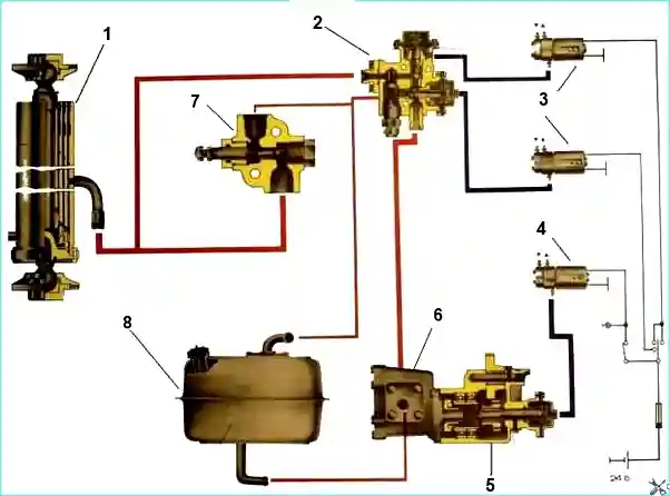
When maintaining the hydraulic system, you should check the oil level in the tank with the platform lowered using the indicator built into the tank cover.
The level should be between the “H” and “B” marks on the indicator
During seasonal maintenance, the oil in the hydraulic system should be changed.
To drain the oil, unscrew the drain plug; to more completely empty the system, disconnect the hose from the suction pipe of the oil pump.
To fill the hydraulic system with oil, unscrew the cap of the oil tank, remove, rinse and reinstall the strainer.
Fill the oil up to the “B” mark marked on the oil level indicator, after which you need to raise and lower the platform 3-4 times at an average crankshaft speed (1100-1300 rpm) to remove air from the system.
After this, check the oil level and, if necessary, add to the “B” mark.

For a gear pump, cavitation is dangerous - the release of gases and vapors from the liquid (boiling of the liquid).
In this case, vapor-gas bubbles are formed in the rarefaction zone, which move to the compression zone and are destroyed there, causing mechanical damage in the pump (damage to gear surfaces).
Cavitation causes increased noise and vibration of the pump.
Cavitation is caused by the following reasons:
- - leakage of the suction pipeline, which leads to air entering the suction zone;
- - clogged oil tank filters and insufficient oil level, foaming, clogged breather.
To prevent cavitation, it is necessary to ensure the tightness of the pipelines and the cleanliness of the oil tank breather;
- - add oil to the required level in a timely manner;
- - fill the system with oil appropriate for the season; in the cold season, you cannot immediately turn on the pump at maximum speed and under operating load; you must let it idle to warm up the oil in the hydraulic system and thus reduce its viscosity.
If necessary, the platform lifting angle is set with an adjusting screw on the platform lift limiting valve so that the platform of the KamAZ-5511 dump truck stops when the holes of the subframe and the platform for the locking pins are aligned.
The lifting angle of the platform of the KamAZ-55102 dump truck is limited to 48-50° when tipping it both to the right and to the left.


