The automatic brake force regulator is designed to automatically regulate the braking forces on the wheels of the rear bogie depending on changes in the axial load on them and accelerating the release of the wheels of this bogie
Regulation of braking forces is achieved by changing the air pressure in the brake chambers of the wheels of the rear bogie, depending on the actual axial load during braking.
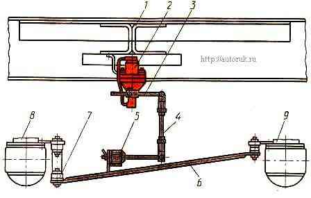
The regulator is installed on the car frame. Its lever 3 with a rod 4 through an elastic element 5 and a rod 6 is connected to the beams of the bridges 8 and 9 of the rear bogie so that their distortions during braking on uneven roads and twisting from the action of the braking torque do not affect the regulation of braking forces.
The elastic element protects the regulator from damage during vertical movements of the rear bogie axles, and also absorbs shocks and reduces vibration when they exceed permissible limits.
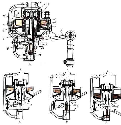
The regulator consists of valve 1 (Fig. a), valve pusher 4 with a drive (shaft with a ball joint 7), piston 2 with inclined ribs 3, membrane 6 connected to piston 2 and clamped by a connector of the upper and lower housings, piston 8, guide 9, pusher 4, insert 10 with inclined ribs 11 and connecting tube 12.
The inclined ribs 3 of the piston enter the space between the inclined ribs 11 of the insert.
The piston ribs and inserts have an opposite slope to the piston axis.
Through connecting tube 12, compressed air enters under piston 8, which ensures smooth operation of the regulator when valve 1 closes the atmospheric outlet.
Terminal “I” of the regulator is connected to the upper section of the brake valve, terminal “II” is connected to the brake chambers of the rear wheels, terminal “III” and cavity A are connected to the atmosphere.
In the initial position (without braking, Fig. 2, b), valve 1 is pressed by its spring to the seat in piston 2.
Terminal “I” is separated from terminal “II” and is connected to the atmosphere through the upper section of the brake valve, and the brake chambers of the rear wheels are connected to the atmosphere through terminal “II”, hollow pusher 4 and terminal “III”.
The position of the pusher is determined by the position of the heel 7.
When braking (Fig. 2, c), compressed air, supplied from the upper section of the brake valve to output I of the regulator, moves piston 2 down, and piston 8 up until it stops at the heel.
In this case, valve 1 is pressed against the outlet seat of pusher 4 and terminal “II” is disconnected from the atmospheric terminal “III”.
Further movement of piston 2 leads to separation of valve 1 from the seat in piston 2.
Compressed air from port “I” enters port “II” and then to the brake chambers of the rear wheels, as well as through the annular gap between piston 2 and guide 9 into the cavity under membrane 6. The latter begins to act on piston 2 from below.
At the moment of reaching pressure in the brake chambers, and consequently in port "II", the ratio of which to the pressure in port "I" corresponds to the ratio of the active areas of the upper and lower sides of piston 2, the latter rises up until valve 1 lands on saddle 2.
The flow of compressed air from terminal “I” to terminal “II” stops, i.e. the regulator’s tracking action is carried out. The action of the piston 8 compensates for the pressure force of the valve 1 on the pusher pad 4.
The active area of the upper side of the piston, which is pressed by compressed air supplied from the upper section of the brake valve to terminal “I”, remains constant; the active area of the membrane on the lower side of the piston, which is pressed by the compressed air entering the brake chambers of the rear wheels (to terminal “II”), is variable due to a change in the relative position of the inclined ribs 3 of the moving piston 2 and the inclined ribs 11 of the fixed insert 10.
The relative position of the piston and insert depends on the position of the lever 5 and the pusher 4 connected to it through the heel 7.
When minimum axial load (the car is unloaded, Fig. d), the distance between the axles and the regulator is greatest and lever 5 with pusher 4 is in the lowest position.
To ensure the supply of compressed air to terminal “II”, piston 2 must move downwards as much as possible.
As the piston moves downwards, its ribs 3 fall below the ribs 11 of the insert and the diaphragm 6 is superimposed on the inclined ribs of the piston.
The active area of the membrane 6, acting on the piston 2 from below, becomes maximum.
In this case, the ratio of the active areas of the upper and lower sides of the piston 2, and therefore the pressure difference in the terminals “I” and “II” become the largest.
In other words, to balance the forces acting on piston 2 from above and below, it is necessary that the pressure in terminal “II” (in the brake chambers) be less than in terminal “I”. Thus, when the car is completely unloaded, the pressure in port "II" is approximately three times less than the pressure in port "I".
At full axial load (Fig. c), the distance between the axles and the regulator is the smallest and lever 5 with pusher 4 is in the upper position.
The supply of compressed air to terminal “II” is ensured by a slight downward movement of the piston 2 without the piston ribs 3 exiting below the insert ribs 11.
In this case, membrane 6, which is under pressure from compressed air, rests only on the ribs of the insert and the force from it is not transmitted to piston 2.
The active areas of the upper and lower sides of the piston in this case are equal; therefore, the pressure in terminals “I” and “II” to balance the forces acting on piston 2 from above and below must be equal, i.e., what pressure is at terminal “I”, the same will be at terminal “II” .
The intermediate position of the lever 5 is characterized by a change in the active area of the membrane 6, since when the piston 2 moves downward, its inclined ribs 3 protrude below the inclined ribs 11 of the insert.
Moreover, the angle of inclination of the ribs is selected so that the active area of the membrane and the pressure in the brake chambers change according to a dependence close to linear at different positions of the lever.
In other words, lever 5 and piston 2 move downward as the axle load of the vehicle decreases.
As a result, the active area of membrane 6 increases, and the pressure in the brake chambers decreases.
So, the brake force regulator automatically maintains compressed air pressure in terminal “II” and the associated brake chambers, which provides a braking force proportional to the actual axial load at a given moment.
When the brake is released, the pressure in terminal "I" decreases.
Piston 2, under the pressure of compressed air, moves from bottom to top through membrane 6, and valve 1 sits on the seat of piston 2, closing the inlet hole.
With further movement of piston 2, valve 1 moves away from the seat of pusher 4 and compressed air from the brake chambers through outlet “II”, hollow pusher 4 and outlet “III” escapes into the atmosphere.
Air from the outlet cavity / is vented to the atmosphere through the atmospheric valve of the brake valve.