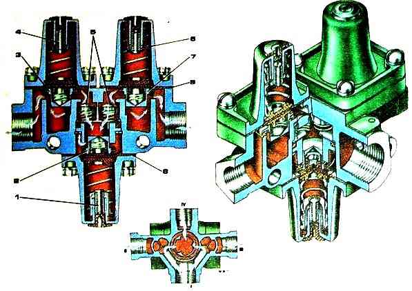
The triple safety valve serves to divide the line from the compressor into three autonomous circuits - two main (front axle wheel brake drive and rear bogie wheel brake drive) and one additional (emergency brake release system drive), as well as to automatically shut off the damaged circuit with in order to maintain pressure in serviceable circuits
The triple safety valve consists of a body 1, three covers 2, three valves 3, 6 and 8, three diaphragms 5 and two bypass valves 7.
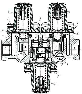
Compressed air from the compressor through the housing outlet enters cavities “A” and “B” under valves 3 and 6.
When the pressure in the cavities reaches 520 kPa, valves 3 and 6, overcoming the forces of the balancing springs 4 and bending the membranes 5, open.
Compressed air through terminals “I” and “II” is directed to the receivers of the brake drive circuits of the wheels of the front axle and rear bogie, respectively.
Simultaneously with the start of filling the receivers, valves 7 open and air enters the cavity above valve 8.
When the pressure reaches 510 kPa, valve 8 opens and compressed air fills the circuit of the emergency brake release system.
If the pneumatic drive circuits are in good working order, the membranes 5 additionally bend under the influence of air pressure in cavities A, B and C.
Therefore, valves 3, 6 and 8 are open even when the pressure in these cavities is below the specified value.
If one of the circuits fails, for example circuit “I”, the pressure in the internal cavity of the faulty circuit (in terminal “I”) decreases and valve 3 closes under the action of spring 4.
But since air from the compressor continues to flow into the cavity under valves 3, 6 and 8, and compressed air from the receivers acts on the membranes of serviceable circuits, valves 6 and 8 of serviceable circuits open at a pressure less than the opening pressure of the valve in the faulty circuit, and no air will flow into the leaking circuit.
When the air pressure at the inlet to the valve body reaches above the set value, the valve of the leaky circuit will open and excess air will be released into the atmosphere, i.e. in the sealed circuits the pressure will be maintained corresponding to the opening pressure of the valves of the leaky circuit (520 or 510 kPa).
If the line coming from the compressor fails, valves 3, 6 and 8 are closed under the action of springs 4 and the pressure in the pneumatic drive circuits is maintained.
Receivers serve to accumulate compressed air and supply it to brake pneumatic drive devices, as well as to power other consumers and vehicle systems.
The cars are equipped with six receivers with a volume of 20 liters, four of them are connected in pairs, forming a single volume of 40 liters.
The receivers are installed on the car frame brackets and attached to them with clamps.