The injection pump supplies the injector of each cylinder with strictly dosed portions of fuel under high pressure in accordance with the operating procedure and the specified mode
The fuel pump is installed between the banks of cylinders and is driven by the camshaft gear through an automatic fuel injection advance clutch.
For two revolutions of the crankshaft, the pump camshaft makes one revolution.
The pump operation is controlled by the driver from the cab and is automatically adjusted by an all-mode crankshaft speed controller depending on the engine load.
The regulator is built into the pump design.
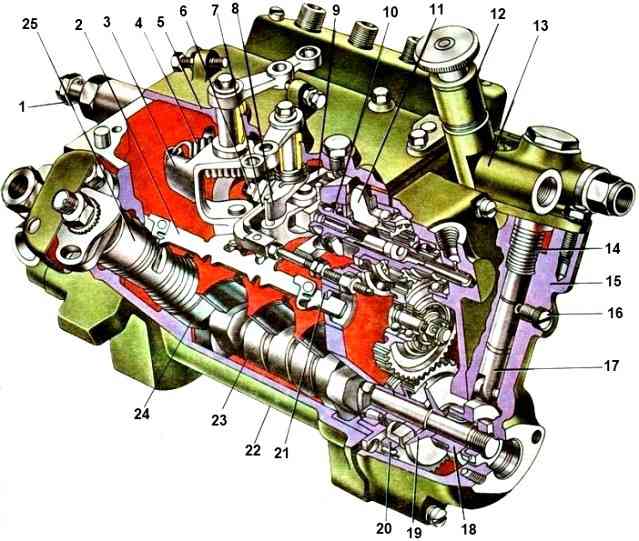
The main parts of the high-pressure pump (Fig. 1.) are housing 22, cam shaft 23 and eight discharge sections, each of which serves one cylinder. The pump body is V-shaped, its sections are located at an angle of 75 °.
This design makes it possible to reduce the length of the cam shaft and increase its rigidity.
The pump cam shaft is mounted on two tapered roller bearings.
The outgoing end of the shaft is sealed with a rubber seal.
On the same side, on the tail of the shaft, a fuel injection advance clutch is fixed, through which the pump is driven, and at the rear end of the shaft, gears 20 for driving the speed controller, a damper and an eccentric 18 for driving the low-pressure fuel pump are fixed.
Pushers 24 are installed in the lower part of the body and are secured against rotation by crackers that fit into grooves made in the sockets.
Next to the sections, two rails are installed in guide bushings 21: left and right.
On one side, each rack is connected to four bushings of the fuel injection pump sections, and on the other, it is engaged with the levers of the crankshaft speed regulator, which controls the amount of fuel supplied.
Fuel is supplied to the high-pressure pump from the fine filter through a fitting and a hollow bolt with which it is connected to the low-pressure fuel line.
Fuel circulates through inlet and outlet channels drilled in the housing along each row of discharge sections.
The pressure in the channels is maintained within 50-110 kPa by ball bypass valve 1, which is installed on the front wall of the housing.
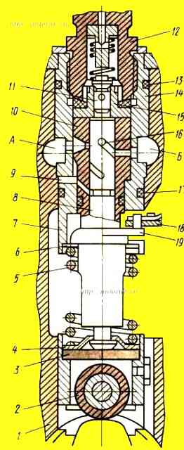
Each section of the high-pressure fuel pump consists of a plunger 8 (Fig. 2) and a bushing 10, which are individually fitted to each other and form a movable connection with minimal clearance.
Such a precision pair practically prevents fuel leakage during its injection; it cannot be disassembled.
The plunger bushing is installed in the body of section 14 and is kept from turning by pin 9.
The spring rests at one end through the support washer 6 into the body, and at the other end into the plate 4, which captures the shank of the plunger and attracts it to the heel 3 of the pusher, without interfering with the free rotation of the plunger around its axis.
A rotary sleeve 19 is loosely placed on the plunger sleeve, which has a pin in the upper part connected to the rack 18, and in the lower part there are two grooves into which the splined protrusions of the plunger fit. Thus the plunger The rod is connected to the rail.
When the rack moves longitudinally, all plungers rotate at the same angle.
The axial channel of the plunger is connected by radial holes with two screw grooves. The upper edge of a carefully processed groove is called a cut-off edge.
The opposite, less precisely machined groove is false and equalizes the lateral pressure of fuel on the plunger, thereby reducing wear on it and the bushing.
In the middle part of the plunger there is an annular groove that collects fuel that has leaked through the gap between the bushing and the plunger.
The bushing has a drainage hole through which fuel is discharged from the annular groove into the fuel channel of the pump housing.
The lower annular groove on the plunger distributes the leaked fuel along the bushing as a lubricant.
Discharge valve 11 and its body 15 are also a precision pair, separating the above-plunger cavity of the sleeve 10 from the fuel line through which fuel is supplied to the injector.
The valve and its body are secured using fitting 12 and a spring.
The spring presses the valve to the body with one end, and the other rests against the stop, which simultaneously serves as a valve lift limiter.
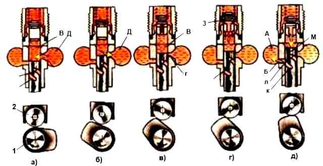
The filling of the above-plunger cavity “B” (Fig. a) in the bushing with fuel occurs when the plunger moves downwards, when it opens the inlet hole, from this moment the fuel begins to flow into the cavity “B” above the plunger, since it is under pressure 50 -110 kPa.
When the plunger moves upward under the action of the oncoming cam 1 (Fig. b), at the beginning some of the fuel is displaced back into channel “D”, but as soon as the end edge of the plunger closes the inlet hole “G” (Fig. c), reverse bypass fuel stops and the pressure of the remaining fuel locked in the above-plunger cavity increases sharply.
When the pressure reaches 0.9-1.1 MPa, discharge valve 3 opens (Fig. d), which corresponds to the start of fuel supply, which flows through the high pressure fuel line to the nozzle.
When the fuel pressure at the injector inlet becomes sufficient to lift the needle, a dose of fuel is injected from the injector into the cylinder.
Fuel injection will continue until the cut-off edge "A" approaches the bottom of the cut-off hole "B" (Fig. e) of the bushing, connecting the above-plunger cavity with the outlet channel "A".
At this moment, fuel is cut off (quickly stops injection), it flows through the axial channel M and groove K of the plunger into the cut-off hole “B” of the bushing and further into channel “A”, the pressure above the plunger drops sharply and the injection valve quickly closes .
When the radial drilling of the discharge valve is completely blocked by the edge of the housing, the valve, lowering, begins to suck fuel from the fitting, so its supply to the nozzle abruptly stops.
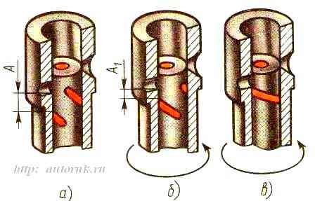
As the engine load changes, the amount of fuel injected into the cylinders must change. It is regulated by changing the active stroke of the plunger while maintaining a constant overall stroke.
The active stroke of the plunger corresponds to distance A (Fig. 4a) in height from the bottom of the cut-off hole to the cut-off edge at the moment when the plunger closes the inlet hole.
If the plunger is turned to the right (Fig. 4), its active stroke will be shortened, the cutoff will occur earlier and less fuel will be supplied.
If you turn the plunger again in the same direction (Fig. 4c), the groove will be located after the shut-off hole and the above-plunger cavity will be in communication with this hole throughout the entire stroke of the plunger.
Therefore, fuel will not be supplied to the injector; the supply is turned off.
Thus, when the plunger is turned, the moment at which the supply ends and the amount of fuel supplied changes, but the moment at which the pump begins supplying fuel remains unchanged.
The moment at which the section begins to supply fuel is adjusted by selecting the heel 3 (see Fig. 2) of the pusher of the required thickness.
When installing a thicker heel, fuel begins to flow earlier, and a thinner one later.
Such adjustment of the pump is carried out on a special stand, where you can adjust the fuel supply of each section, for which you turn Place the section body together with the plunger bushing (with a stationary rack) behind the flange, having previously loosened the fastening nuts.
When the section body is turned counterclockwise, the cyclic feed increases, and when turned clockwise, it decreases.
")

")
")
")
")
")
")
")