Pneumatic clutch booster KamAZ
The pneumatic amplifier is mounted on the clutch housing on the right side of the power unit. The amplifier housing consists of two parts
The front 14 part of the body is made of aluminum alloy, and the rear 16 is made of cast iron.
A gasket is installed between these parts, which is also the membrane 9 of the tracking device located on top.
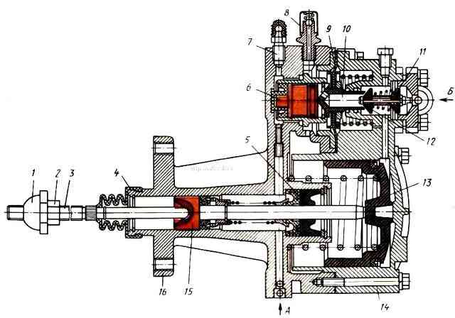
The tracking device automatically changes the air pressure on the pneumatic piston 13 depending on the pressure in the clutch hydraulic drive.
The main parts of the follower device include follower piston 6 with a cuff, inlet 11 and outlet 12 valves (valve block), membrane 9 and springs.
When the clutch pedal is released (the clutch is engaged), the pneumatic piston 13 and the clutch release piston 15 are in the extreme right (front) position (the pneumatic piston occupies this position under the influence of the return spring).
The pressure in the cavity in front of the piston and behind the piston corresponds to atmospheric pressure.
The position of the clutch release piston 15 is determined by the stop of its pusher in the bottom of the pneumatic piston.
In the follower, the outlet valve 12 is open and the inlet valve 11 is closed.
When you press the clutch pedal, the working fluid flows under pressure to hole “A”, creating pressure in the cavity of the clutch release cylinder and at the end of the follower piston 6.
Under the pressure of the working fluid, the follower piston acts on the valve block, closing the outlet valve 12 and opening the inlet valve 11.
Compressed air supplied through pipelines to hole “B” begins to flow into the pneumatic cylinder.
Under the pressure of compressed air, the pneumatic piston 13 moves, acting on the piston rod.
As a result, a total force acts on the pusher 3 of the clutch release piston 15, ensuring complete disengagement of the clutch when the driver presses the pedal with a force of 150 N.
When the pedal is released, the pressure in front of the follower piston 6 drops, as a result of which the inlet valve in the follower device closes and the outlet valve opens.
Compressed air from the pneumatic cylinder is gradually released into the atmosphere, the pressure drops, liquid from the hydraulic cylinder flows into the main cylinder and the clutch mechanism is activated.
In the absence of compressed air in the pneumatic system, the ability to control the clutch remains possible, since the clutch can be released using the pressure in the hydraulic part of the amplifier. But at the same time, the pedal force created by the driver should be about 600 N.
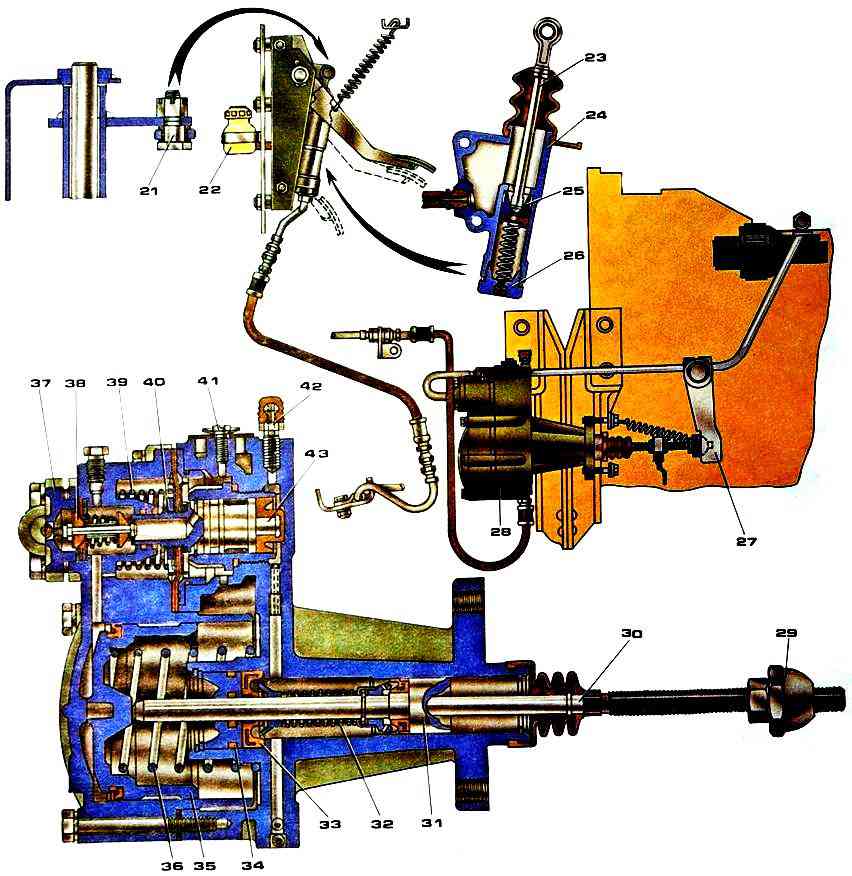
When replacing the pneumatic hydraulic booster for the clutch drive, to remove the pneumatic hydraulic booster:
- - release air from the drive circuit of the auxiliary brake system and other consumers through the valve on the receiver;
- - remove the release spring of the clutch release fork shaft lever, disconnect the power steering air pipe, hydraulic hose and drain the fluid from the hydraulic drive system;
- - unscrew the two bolts securing the pneumatic hydraulic booster and remove the booster with the rod.
To install a pneumatic hydraulic booster:
- - align the mounting holes with the holes in the clutch housing and secure the amplifier with two bolts and spring washers;
- - connect the hydraulic hose of the pneumatic power steering and the air pipeline;
- - install the fork shaft tension spring in disengaging the clutch.
Pour brake fluid into the master cylinder compensation tank and bleed the hydraulic drive system.
Check the tightness of the pipeline connections (leaking of brake fluid from the connections is not allowed), if necessary, eliminate the leakage by tightening or replacing individual elements of the connections.
Check and, if necessary, adjust the gap between the end of the cover and the travel limiter of the gear divider valve rod.
")

")
")
")
")
")
")
")