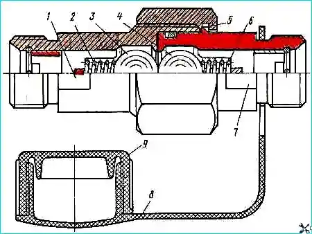
The locking device, designed to connect the hydraulic system of the KamAZ-55102 dump truck-tractor with the hydraulic system of the trailer, consists of two buildings 1 and 7, one of which is connected to the discharge line of the tractor, the other - to the trailer.
In the case of a dump truck operating with a trailer, both parts are connected to each other by nut 5.
In this case, the balls 3 and 4 of the shut-off valves are pressed by each other from the support belts and do not interfere with the flow of oil.
When working without a trailer, you need to disconnect its line; to do this, simply unscrew the nut.
In this case, the balls, under the influence of springs, will block the holes in the housings and prevent oil from leaking out of the hydraulic system
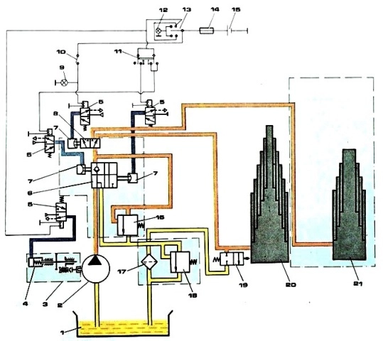
Operation of the hydraulic system of the platform lifting mechanism
The hydraulic system of the platform lifting mechanism works as follows.
To turn on the power take-off, disengage the clutch and put switch 13 in the on position (indicator lamp 14 lights up).
The current through the thermobimetallic fuse 16 is supplied to the winding of the electromagnet of the electropneumatic valve 6, the core of which, moving, opens the valve.
Air from the pneumatic system enters the cavity of the pneumatic chamber 4 of the power take-off.
When the clutch is engaged, oil pump 2 starts working.
Oil from tank 1, through the suction and discharge cavities of the pump, flows through a pipeline into control valve 7, and then drains into the tank.
Such oil circulation helps to warm it up in winter, which improves the operating conditions of the hydraulic system of the lifting mechanism.
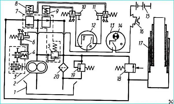
To raise the platform of the KamAZ-5511 dump truck, switch switch 12 to position 11.
In this case, the current passes through the windings of electro-pneumatic valves 10 and 11, the cores of which, moving, open the valves.
Air from the pneumatic system is supplied to pneumatic chambers 8 and 9 of control valve 7.
Oil from the control valve flows through pipelines into hydraulic cylinder 17.
Under oil pressure, the hydraulic cylinder links sequentially extend, raising the platform.
As the platform rises, the hydraulic cylinder tilts; When the maximum tilt angle is reached, the hydraulic cylinder body is pressed on the adjusting screw of the platform lift limiting valve 18 and the oil is drained through the valve into the tank.
Platform lifting stops.
To stop the platform in an intermediate position, move switch 12 to the neutral position.
In this case, the electro-pneumatic valves 10 do not turn off, the air leaves the working cavities of the pneumatic chambers 8 and 9 into the atmosphere, the hydraulic cylinder line is closed, and the discharge cavity of the control valve communicates with the drain line and the oil from the pump is drained through the control valve into the tank.
To lower the platform, switch 12 is moved to position 1. The current passes through the winding of the electro-pneumatic valve 6, the core of which, moving, opens the valve.
Air from the pneumatic system enters pneumatic chamber 8 of the control valve, and oil is drained from the hydraulic cylinder into the tank through the control valve.
After finishing lowering the platforms, it is necessary to set switch 13 to the off position (after disengaging the clutch). The oil pump stops working.
It should be noted that lowering the platform is possible both when the pump is running and when the oil pump is already turned off by switch 13.
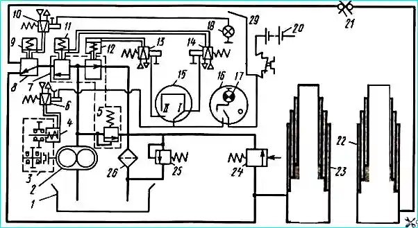
The principle of raising and lowering the platform of the KamAZ-55102 dump truck is similar to the operation of the mechanism for lifting and lowering the KamAZ-5511 platform.
To raise the trailer platform, after turning on the power take-off, turn on switch 19 in the cab of the KamAZ-55102 dump truck (when lifting the tractor platform, it must be turned off); the indicator lamp will light up a 18.
The current flows to the winding of the electromagnet, the core of which, moving, opens the electro-pneumatic valve 10, air from the pneumatic system enters the pneumatic chamber 9 of the hydraulic distributor, the hydraulic cylinder line of the tractor is blocked, but the passage of oil into the hydraulic cylinder 22 of the trailer is opened.
Further operations for raising and lowering the trailer platform are similar to the operations for raising and lowering the tractor platform.
When the trailer platform lifting mechanism has finished operating, switch 19 must be turned off, and the indicator lamp 18 will go out. It should be noted that only alternating operation of the hydraulic cylinders of the tractor and trailer is possible.
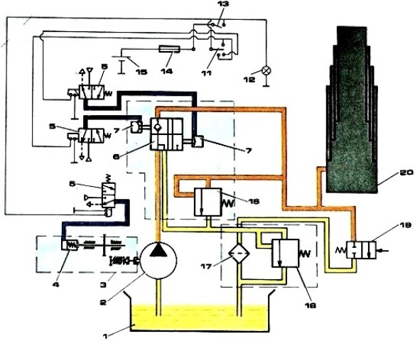
Another scheme for lifting the KamAZ 5511 platform
Another scheme for lifting the KamAZ 55102 platform
")

")
")
")
")
")
")
")