Electro-pneumatic valves serve to distribute compressed air through the pneumatic actuating chambers of the power take-off and control valve
The solenoid valve consists of a body 3, a cover 1, an electromagnet 4, a rod 5, springs 6, valves 8.
Air from the pneumatic system is supplied to terminal “I” into the cavity in the valve cover
When the electromagnet is turned on, the rod, extending, presses the upper valve 8 to the seat of the housing 3.
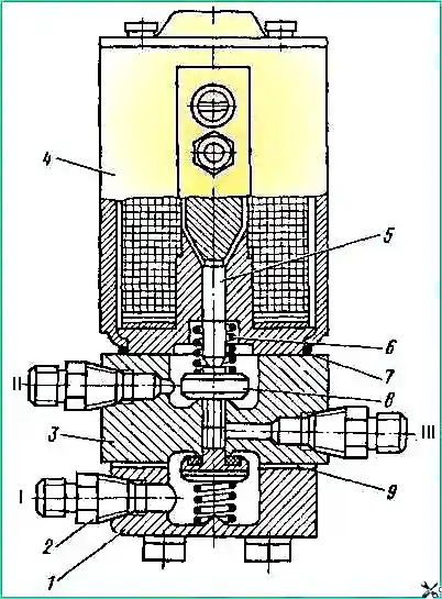
In this case, the lower valve 8 moves away from the seat and air from the cavity in the valve cover through the channel in the body and terminal “III” enters the pneumatic actuating chambers of the control valve or into the pneumatic cylinder body of the power take-off.
When the electromagnet is turned off, the lower valve is pressed by a spring to the housing seat, and the upper valve moves away from the seat.
Air from the pneumatic chamber exits to the atmosphere through outlet “II”.
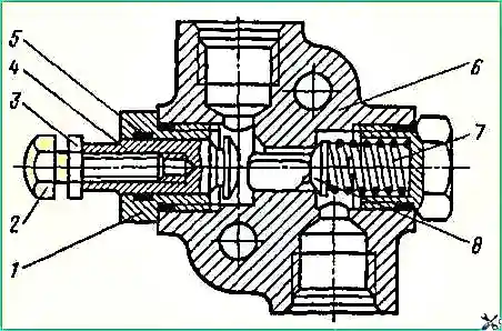
A distributor is attached to the control valve of the KamAZ-55102 dump truck, which serves to distribute the oil flow either to the hydraulic cylinder of the tractor or to the hydraulic cylinder of the trailer.
The body contains seats 6, secured with retaining rings 5.
The threaded end of the valve 8 with a membrane 12 enters the cavity of the pneumatic chamber, closed by a lid 13.
A spring holds the valve in the leftmost position.
The seats of the bushings and valve are sealed with rings 9 and 10, respectively.
Possible leaks through the valve seals are removed on one side through the drain hole of plug 4, on the other through the hole in the pneumatic chamber under the membrane.
The oil passes through the hole in the distributor body under valve 7 through the seat, fitting and enters the hydraulic cylinder line of the dump truck.
When compressed air is supplied to the cavity of the pneumatic chamber above the membrane, valve 8 moves to the right, the hydraulic cylinder line of the dump truck closes and oil begins to flow through fitting 2 into the trailer hydraulic cylinder line.
")

")
")
")
")
")
")
")