The engine air supply system consists of a filter, a seal, an air intake, and pipes and tubes connecting the air intake and air cleaner to the turbochargers.
Its design is determined by the vehicle configuration.
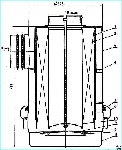
Air filter: 1 - pre-cleaner; 2 - filter element; 3 - housing; 4 swirl; 5 - sealing ring; 6 latch; 7 hopper partition; 8 - cover; 9 - plug; 10 - nut
The air filter (Figure 1) is a dry type, two-stage filter designed to clean the air entering the engine from dust.
It consists of a housing 3 with a swirl 4, a cover 8, a pre-cleaner 1, a filter element 2. The tightness of the connection of the cover with the housing is ensured by a sealing ring 5.
The cover is attached to the housing with four spring latches 6. The main parts of the filter are made of sheet steel
1.2 mm thick. To increase the efficiency of cleaning the air entering the engine, a pre-cleaner 1 is put on the filter element - a shell made of non-woven filter fabric.
Air cleaning in the filter is two-stage.
The first stage of cleaning is a monocyclone containing a swirler 4 installed behind the inlet pipe and providing a screw movement of the air flow in the annular gap between the filter housing and element 2.
Due to the action of centrifugal forces, dust particles are thrown to the wall of the housing and driven into the bin.
The dust collection bin is formed by a cover 8, a partition 7 and a removable plug 9.
The second stage of cleaning is a filter element 2, which has outer and inner casings.
They are made of perforated steel sheet and corrugated filter paper, connected at the ends by metal covers, which are glued with special glue.
The filter element is tightly pressed to the bottom of the housing 3 and sealed with an end rubber ring.
The filter element is fastened in the housing with a self-locking nut 10.
The air, pre-cleaned in the first stage, enters the second stage with a replaceable cardboard filter element for finer cleaning, where, penetrating through the pores of the cardboard, it leaves small dust particles on its surface.
The purified air through the tee enters two centrifugal compressors and, under excess pressure, through the charge air cooler pipe into the engine cylinders.
The engine air supply system is equipped with an indicator of filter element clogging.
If the clogging indicator is triggered, it is necessary to service or replace the air filter element.
Gas turbine system supercharging and cooling of the charge air, by using part of the energy of the exhaust gases, provides the supply of pre-compressed and cooled air to the engine cylinders.
Supercharging increases the charge density of the air entering the cylinders and burns more fuel in the same working volume and increases the engine power per liter.
The use of supercharged engines expands the operational capabilities when driving on long climbs, over rough terrain and in mountainous conditions.
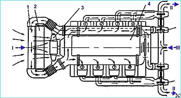
Diagram of the gas turbine supercharging and charge air cooling (CAC) system: 1 - heat exchanger; 2 - cooling system radiator; 3 - fan; 4 - engine; I - air inlet; II - exhaust gas outlet through the compressor turbine; III - air supply after the air cleaner
The engine gas turbine supercharging system (Figure 2) consists of two interchangeable turbochargers (TCR), exhaust and intake manifolds and pipes, an air-to-air charge air cooler (CAC), supply and outlet pipelines.
Air enters the turbocharger's centrifugal compressor from the air cleaner, is compressed and supplied under pressure to the CAC, and then the cooled air enters the engine.
Turbochargers are installed on the exhaust pipes, one for each bank of cylinders. The exhaust manifolds and pipes are made of high-strength cast iron.
The gas joints between the mounting flanges of the turbocharger turbine, exhaust pipes and manifolds are sealed with heat-resistant steel gaskets.
The gaskets are single-use parts and are subject to replacement during system overhauls.
The gas joint between the exhaust manifold and the cylinder head is sealed with a gasket made of asbestos-steel sheet edged with metal plating bath tape.
The exhaust manifolds are made of one piece and are attached to the cylinder heads with bolts and secured with lock washers.
To compensate for angular movements that occur during heating, special spherical washers are installed under the heads of the exhaust manifold mounting bolts.
The turbocharging and charge air cooling system of the engine must be sealed.
A leak in the system leads to an increase in the heat stress of the parts, a decrease in the power and service life of the engine.
In addition, a leak in the intake tract leads to "dust" wear of the cylinder-piston group and premature failure of the engine.
The bearings of the turbochargers are lubricated from the engine lubrication system through fluoroplastic tubes with a metal braid.
Oil is drained from the turbochargers through steel tubes into the crankcase engine.
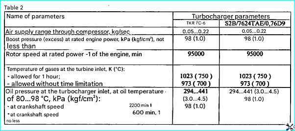
The engine is equipped with two TKR 7S-6 turbochargers.
Instead of the TKR7S-6 turbocharger, S2B/7624TAE/0.76D9 turbochargers from Schwitzer can be installed.
Technical characteristics of the turbochargers are given in Table 2.
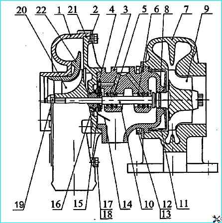
TKR7S-6 turbocharger: 1 - compressor housing; 2 - cover; 3 - bearing housing; 4 - thrust bearing; 5 - bearing; 6 - retaining ring; 7 - turbine housing; 8 - sealing ring; 9 - turbine wheel; 10 - rotor shaft; 11 - turbine screen; 12 - bar; 13 - bolt; 14 - oil deflector screen; 15 - bushing; 16 - oil deflector; 17 - bar; 18 - bolt; 19 - nut; 20 - compressor wheel; 21 - sealing ring; 22 diffuser.
The TKR 7S-6 turbocharger consists of a centripetal turbine and a centrifugal compressor connected to each other by a bearing assembly.
A turbine with a two-pass casing 7 (Figure 3) made of high-strength cast iron converts the energy of the exhaust gases into kinetic energy of the turbocharger rotor rotation, which is then converted into air compression work in the compressor stage.
The turbocharger rotor consists of a turbine wheel 9 with a shaft 10, a compressor wheel 20, an oil deflector 16 and a sleeve 15, secured to the shaft with a nut 19.
The turbine wheel is cast from a heat-resistant alloy using investment patterns and welded to the shaft friction.
The compressor wheel with backward curved blades in the direction of rotation is made of aluminum alloy and, after mechanical processing, is dynamically balanced to a value of (0.4 g mm).
The bearing journals of the rotor shaft are hardened by high-frequency current to a depth of 1-1.5 mm.
After mechanical processing, the rotor is dynamically balanced to a value of (0.5 g mm).
Technical characteristics of turbochargers
The bushing, oil deflector, compressor wheel are installed on the rotor shaft and tightened with a nut with a torque of 7.8-9.8 Nm (0.8-1.0 kgfm).
After assembly, the rotor is not additionally balanced, only the radial runout of the shaft journals is checked.
If the radial runout value is no more than 0.03 mm, marks are applied to the rotor parts in one plane, and the rotor is allowed to assemble the turbocharger.
When installing the rotor in the bearing housing, it is necessary to align the marks on the rotor parts. The rotor rotates in bearings 5, which are floating rotating bushings.
The axial movements of the rotor are limited by thrust bearing 4, clamped between bearing housing 3 and cover 2. The bearings are made of bronze.
The turbocharger bearing housing is made of a cast iron housing and an aluminum alloy cover to reduce heat transfer from the turbine to the compressor.
A heat-resistant steel screen 11 is installed between the turbine housing and the bearing housing to reduce heat transfer.
An oil-slinging screen 14 is installed in the bearing housing, which, together with elastic split rings 8, prevents oil leakage from the housing cavity.
A rubber sealing ring is installed in the "compressor housing - bearing housing" connection to eliminate air leaks. 21.
The turbine and compressor housings are attached to the bearing housing using bolts 13, 18 and strips 12, 17.
This design allows the housings to be installed at any angle to each other, which in turn facilitates the installation of the turbocharger on the engine.
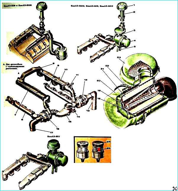
For a vehicle with a turbocharged KAMAZ-5511 engine: 1 - Cap; 2 - Air intake pipe; 3 - Seal; 4 - Air cleaner; 5 - Bracket; 6, 9 - Exhaust manifolds; 7, 10 - Intake manifolds; 8 - Connecting pipe; 11 - Intake manifold pipe; 12 - Right turbocharger; 13 - Right exhaust pipe; 14 - Air cleaner clogging indicator; 15 - Tee; 16 - Left turbocharger; 17 - Left exhaust pipe; 18 - Filter element fastening nut; 19 - Filter element holder; 20 - Air cleaner cover; 22 - Air cleaner housing with dust deflector; 21 - Filter element; 23 - Air intake cap; 24 - Disc; 25 - Signal drum
Maintenance of the turbocharger system and intercooler
During engine operation, the tightness of the exhaust gas line and air supply to the engine is checked by visual inspection.
The reliability of fastening of parts and units of these systems is periodically checked, and if necessary, the bolts, fastening nuts and clamps are tightened.
The operation of the turbocharger has a significant impact on the parameters and performance of the engine.
A turbocharger malfunction can lead to engine failure.
Despite the fact that turbochargers do not require adjustments during operation, it is necessary to systematically follow the rules for engine maintenance established by the manufacturer and periodically monitor the operation of the turbochargers by ear.
During TO-2, it is necessary to check the ease of rotation of turbocharger rotors.
To do this, remove the exhaust pipe.
Then check by hand how the rotor rotates in its extreme axial and radial positions.
The rotor should rotate easily, without jamming or touching the stationary parts of the turbocharger.
Turbocharger bearings are very sensitive to the amount and purity of oil, so the necessary conditions for the normal operation of the bearing unit are timely replacement of oil and filter elements of the engine oil filter, as well as the use of oil grades recommended by the manufacturer.
During seasonal maintenance, it is recommended to remove the turbochargers from the engine once every two years to clean the centrifugal compressor.
It is advisable to remove the unit together with the exhaust manifold.
The centrifugal compressor must be cleaned as follows sequences:
- apply combined marks on the end surfaces of the compressor body and cover.
Unscrew the compressor body mounting bolts. Remove the compressor body by lightly hitting the bosses with a wooden hammer.
Inspect the rubber sealing ring in the cover groove.
If defects are found (cuts, loss of elasticity), replace the sealing ring with a new one;
- - inspect the compressor wheel blades. If traces of contact with the compressor housing, deformation of the blades or their destruction are detected, the turbocharger is subject to repair at a specialized enterprise or replacement;
- - wash the internal cavity of the compressor housing, the surface of the cover with a rag soaked in diesel fuel.
When cleaning the compressor wheel, it is recommended to clean the interblade surfaces with a hair brush using diesel fuel;
- - check the ease of rotation of the rotor, jamming of the rotor is not allowed;
- - before assembly, it is necessary to lubricate the sealing ring with engine oil, align the marks, install the compressor housing on the cover disk, tighten the bolts with a torque wrench.
Check the ease of rotation of the rotor again. In extreme axial and radial positions, the rotor wheels must not contact the housing parts.
Since the turbocharger rotor is balanced with high precision, complete disassembly, repair and maintenance of the supercharging units must be carried out at specialized enterprises that have the necessary equipment, tools, devices, instruments and qualified personnel.
During seasonal maintenance, it is necessary to drain the condensate accumulated in the CVD.
")

")
")
")
")
")
")
")