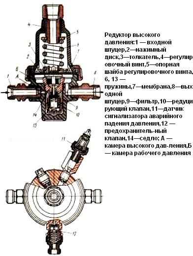
The high pressure reducer is designed to reduce the pressure of compressed gas to 0.95 ... 1.1 MPa by one-stage expansion; has a safety valve 12 (fig.1),
triggered at a pressure at the outlet of the reducer 1.45 ... 1.7 MPa, sensor 11 of the signaling device for gas production in cylinders, triggered at a pressure of 0.45 ... 0.55 MPa at the inlet to the reducer, ceramic filter 9 , trapping mechanical particles (corrosion products, scale) at the inlet to the gearbox.

The compressed gas through the inlet fitting 1 and the filter 9 enters the valve 10, which is under the pressure of two springs: 13 acting directly on the valve, and 6, which transmits force to the valve through the disk 2 of the membrane 7 and the pusher 3.
Due to the fact that the force of the spring 6 is greater than the force of the spring 13, the valve 10 is open and the gas enters the operating pressure chamber B through the seat 14.
Disruption of the balance of gas flow and inflow into chamber B is accompanied by a change in pressure in it.
As a result of the action of the control system, the working pressure is restored to the set one.
When the gas flow rate decreases or its inlet pressure increases, more gas enters cavity B than it leaves the reducer, and its pressure in it increases.
At the same time, the membrane 7 rises and the gap between the seat 14 and the valve 10 decreases, as a result, less gas enters the cavity B and its working pressure is restored.
When the gas pressure in this chamber reaches 0.95 ... 1.1 MPa, the action of the spring 6 on the pusher stops and the valve 10 closes under the action of the spring 13.
The tightness of the valve-seat pair is ensured by a diflo valve seal.
When gas flows out of the working pressure chamber, the reduction process resumes.


