The cooling system is designed to ensure optimal thermal conditions for engine operation
The engine cooling system is liquid, closed type, with forced circulation of coolant (coolant)
The main units and components of the cooling system include: radiator, fan with viscous or hydraulic drive clutch, fan casing, fan cowling, water channel housing, water pump, thermostats, channels and connecting pipelines for the passage of coolant.
The diagram of the cooling system with a fan coaxial with the crankshaft and with a viscous fan drive clutch is shown in Figure 1
During engine operation, the circulation of coolant in the system is created by water pump 8.
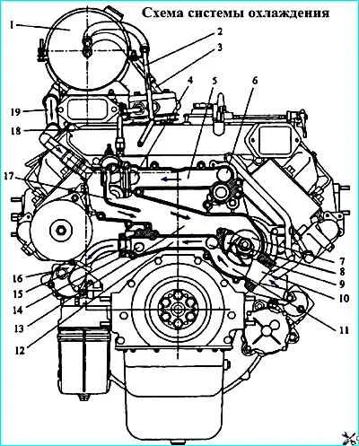
Cooling system diagram: 1 - expansion tank, 2 - steam outlet pipe; 3 pipe for draining liquid from the compressor; 4 channel for liquid outlet from the right row of cylinder heads: 5 - connecting channel; 6 - channel for liquid outlet from the left row of cylinder heads; 7 - water pump inlet cavity; 8 water pump, 9 channel for liquid inlet to the left row of cylinder liners: 10 channel for supplying liquid to the water pump from the radiator; 11 outlet cavity of the water pump; 12 connecting channel; 13 bypass channel from the water box to the water pump inlet; 14 channel for liquid inlet to the right row of cylinder liners; 15 channel for liquid drainage into the oil heat exchanger; 16 oil heat exchanger; 17 - water box; 18 pipe for liquid supply to the compressor; 19 bypass pipe
The coolant from pump 8 is pumped into the cooling cavity of the left cylinder bank through channel 9 and through channel 14 into the cooling cavity of the right cylinder bank.
Washing the outer surfaces of the cylinder liners, the coolant enters the cooling cavities of the cylinder heads through holes in the upper mating surfaces of the cylinder block.
From the cylinder heads, the heated liquid enters the water box of the water channel housing 17 through channels 4, 5 and 6, from which, depending on the temperature, it is directed to the radiator or to the pump inlet.
Part of the liquid is diverted through channel 15 to the oil heat exchanger 16, where heat is transferred from the oil to the coolant.
From the heat exchanger, the coolant is directed to the water jacket of the cylinder block in the area of fourth cylinder.
The nominal temperature of the coolant in the system during engine operation is 75...98 °C.
The engine thermal mode is regulated automatically: by two thermostats and a viscous fan drive clutch, which control the direction of the liquid flow and the operation of the fan depending on the coolant temperature at the engine outlet and the air temperature at the radiator outlet.
The water channel housing (Figure 1) is cast from a cast iron alloy and secured with bolts to the front end of the cylinder block.
The inlet 7 and outlet 11 cavities of the water pump, connecting channels 5 and 12, channels 9 and 14 supplying coolant to the cylinder block, channels 4 and 6 draining coolant from the cylinder heads, bypass channel 13, channel 15 for draining coolant into the oil heat exchanger, and cavities of the water box are cast in the water channel housing. 17 for installing thermostats, channel 10 for supplying coolant to the water pump from the radiator.
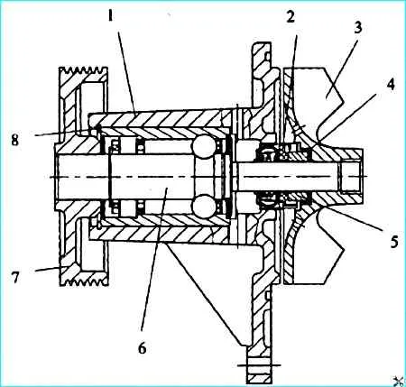
Water pump: 1 housing; 2 oil seal; 3 impeller; sealing cuff; 5 friction ring; 6 - radial ball-roller bearing with roller; 7 - pulley; 8 - thrust ring
The water pump (Figure 2) is of the centrifugal type, mounted on the water channel housing.
A radial double-row ball-roller bearing with a roller 6 is pressed into the housing 1.
The bearing ends are protected by rubber seals on both sides. The bearing is greased by the manufacturer.
No grease refilling is required during operation. The thrust ring 8 prevents the outer race of the bearing from moving in the axial direction.
The impeller 3 and pulley 7 are pressed onto the ends of the bearing shaft.
The seal 2 is pressed into the pump housing, and its sliding ring is constantly pressed by a spring to the sliding ring 5, which is inserted into the impeller through the rubber cuff 4.
There are two openings in the pump housing between the bearing and the seal: lower and upper.
The upper opening is used to ventilate the cavity between the bearing and the seal, and the lower one is used to check the serviceability of the mechanical seal.
Liquid leakage from the lower opening indicates a seal malfunction.
During operation, both openings must be clean, since their blockage will lead to one from bearing failure.
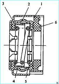
Water pump seal: 1 outer housing; 2 - cuff; 3 spring; 4 inner frame; 5 - outer frame; 6 sliding ring
The water pump seal (Figure 3) consists of a brass outer casing 1, into which a rubber cuff 2 is inserted
Inside the cuff there is a spring 3 with an inner 4 and outer 5 frame
The spring presses the sliding ring 6
The sliding ring is made of graphite-lead hard-pressed antifriction material.
Fan and viscous coupling of the fan drive (Figure 4).
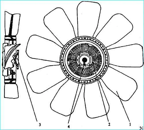
Fan with drive clutch: 1 fan; 2 clutch; 3 hub; 4 - thermo-bimetallic spiral
Nine-blade fan 1 with a diameter of 660 mm is made of glass-filled polyamide, fan hub 3 is metal.
The fan is driven by an automatically engaged viscous clutch 2, which is attached to the fan hub 3.
The clutch operating principle is based on the viscous friction of the liquid in small gaps between the driven and driving parts of the clutch. High-viscosity silicone fluid is used as the working fluid.
The coupling is non-separable and does not require maintenance during operation.
The coupling is engaged when the air temperature at the radiator outlet increases to 61-67 °C. The operation of the clutch is controlled by a thermal bimetallic spiral 4.
The fan is located in a fixed annular shell, rigidly attached to the engine
The fan casing and the fan shell help to increase the flow rate of air pumped by the fan through the radiator.
The fan casing and the fan shell are connected by an annular rubber seal of a U-shaped cross-section.
The radiator is copper-soldered, to improve heat transfer, the cooling tapes are made with louvered perforations, it is attached with side brackets through rubber pads to the frame side members, and with a lower rod to the first cross member of the frame.
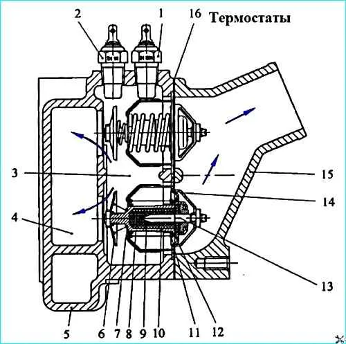
Thermostats: 1 - temperature gauge sensor; 2 emergency overheating alarm sensor; 3 - engine fluid outlet channel; 4 fluid bypass channel to water pump inlet: 5 water box; 6 - bypass valve; 7 - bypass valve spring; 8 rubber insert; 9 - filler; 10 cylinder; 11 main valve spring; 12 main valve; 13 - piston; 14 body; 15 water pipe; 16 gasket
Thermostats (Figure 5) allow to accelerate warming up of a cold engine and to maintain the coolant temperature not lower than 75 °C by changing its flow rate through the radiator.
Two thermostats with the opening start temperature of (80±2) °C are installed in parallel in the water box 5 of the water channel housing.
When the coolant temperature is below 80 °C, the main valve 12 is pressed against the seat of the housing 14 by the spring 11 and blocks the passage of the coolant into the radiator.
The bypass valve 6 is open and connects the water box of the water channel housing via the bypass channel 4 to the inlet of the water pump.
When the coolant temperature is above 80 °C, the filler 9, located in the cylinder 10, begins to melt, increasing in volume.
The filler consists of a mixture of 60% ceresin (petroleum sock) and 40% aluminum powder.
The pressure from the expanding filler is transmitted through the rubber insert 8 to the piston 13, which, being squeezed outward, moves the cylinder 10 with the main valve 12, compressing the spring 11.
An annular passage for coolant into the radiator opens between the housing 14 and the valve 12.
At a coolant temperature of 93 °C, the thermostat opens completely, the valve rises to a height of at least 8.5 mm.
Simultaneously with the opening of the main valve, the bypass valve 6 moves together with the cylinder, which closes the opening in the water box of the water channel housing, connecting it to the inlet of the water pump.
When the coolant temperature drops to 80 °C and below, under the action of springs 7 and 11, valves 12 and 6 return to their original position.
To monitor the coolant temperature, two temperature sensors 1 and 2 are installed on the water box of the water channel housing.
Sensor 1 displays the current coolant temperature on the instrument panel, sensor 2 serves as a coolant overheating indicator.
When the temperature rises to 98-104 °C, the emergency stop indicator light comes on on the instrument panel overheating of coolant.
Expansion tank I (Figure 1) is installed on the engine of KAMAZ vehicles on the right side along the vehicle's direction of travel.
The expansion tank is connected by a bypass pipe 19 to the inlet cavity of the water pump 13, a steam outlet pipe 2 to the upper tank of the radiator and to the pipe for draining liquid from the compressor 3.
The expansion tank serves to compensate for changes in the volume of coolant when it expands from heating, and also allows you to control the degree of filling of the cooling system and helps remove air and steam from it.
The expansion tank is made of translucent propylene copolymer.
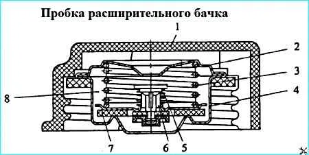
Expansion tank cap: 1 - cap body; 2 - exhaust valve spring plate; 3 - exhaust valve spring; 4 exhaust valve seat; 5 inlet valve spring; 6 inlet valve assembly; 7 exhaust valve gasket; 8 - valve block
The expansion tank cap (Figure 6) with inlet valves 6 (air) and outlet (steam) valves is screwed onto the neck of the tank.
The outlet and inlet valves are combined into the valve block 8. The valve block is non-separable.
The outlet valve, loaded by spring 3, maintains excess pressure of 65 kPa (0.65 kgf/cm 2) in the cooling system, the inlet valve 6, loaded by a weaker spring 5, prevents the creation of a vacuum in the system when the engine cools down.
The inlet valve opens and connects the cooling system with the environment when the vacuum in the cooling system is 1-13 kPa (0.01-0.13 kgf/cm 2).
The engine is filled with coolant through the filler neck of the expansion tank. Before filling the cooling system, you must first open the heating system tap.
To drain the coolant, open the drain taps of the lower elbow of the water pipe, heat exchanger and pump unit of the pre-heater, and unscrew the cap of the expansion tank.
Do not open the cap of the expansion tank on a hot engine, as this may cause hot coolant and steam to escape from the neck of the expansion tank.
Operating the car without the cap of the expansion tank is not allowed.
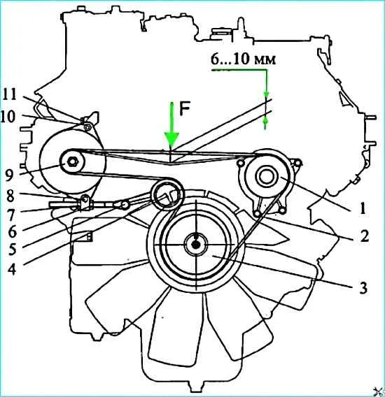
Scheme Checking the tension of the generator and water pump drive belts with the fan located along the crankshaft axis: 1 water pump pulley; 2 - poly V-belt; 3 crankshaft pulley; 4 - tension roller; 5,8,11 bolts; 6, 7, 10 nuts; 9 generator pulley. F= 44.1 ± 5 H (4.5 ± 0.5 kgf).
Adjust the tension (Figure 7) of the poly V-belt 2 of the generator and water pump drive for engines with a fan located along the crankshaft axis as follows:
- - loosen bolt 11 of the rear generator leg, nut 10 of the front generator leg, bolt 8 of the generator bar, bolt 5 of the tension bolt;
- - move nut 6 to ensure the required belt tension; nut 7 fix the position of the generator;
- - tighten bolts 5, 8 and 11, tighten nut 10.
After adjustment, check the tension:
- - a correctly tensioned belt 2 when pressing on the middle of the largest branch with a force of 44.1 ± 5 N (4.5 ± 0.5 kgf) should have a deflection of - 6 ... 10 mm.
Engine configuration with a fluid coupling
For bonnet vehicles, the engine can be equipped with a fan drive fluid coupling located 325 mm above the crankshaft axis.
The system operation diagram is similar to that described above, the design features of such an engine configuration and its components are visible in Figures 8, 9, 10, 11.
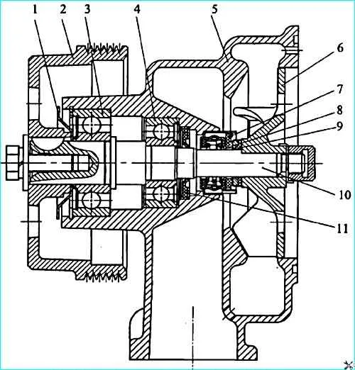
Fan drive fluid coupling (Figure 8)
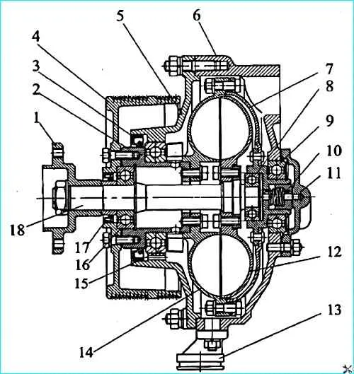
Fan drive fluid coupling: 1 fan hub; 2 - pulley shaft; 3 - seal 740.1318166-01; 4 pulley; 5 bearing housing; 6 bracket housing; 7 drive wheel casing; 8 bearing 204; 9 - bearing 207A; 10 seal; 11 bracket housing cover; 12 - driven wheel; 13 drain pipe; 14 driving wheel; 15 bearing 114; 16 bearing 305; 17 cuff 740.1318186-01; 18 - driven wheel shaft
To maintain optimal engine thermal conditions and save fuel, the fan is driven through a fluid coupling, which is switched on and off automatically depending on the temperature of the liquid in the engine cooling system tel.
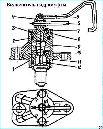
Fluid coupling switch: 1 - switch housing; 2 - sealing ring; 3 - spring; 4 - fork; 5 - rod; 6 - gearbox lever; 7 - cover; 8 - locking ball; 9 - plug; 10 - ball; 11 - thermal power valve; 12 - rod
The fan speed depends on the amount of oil entering the fluid coupling through the switch (Figure 9).
It is installed in the front part of the engine on the branch pipe supplying coolant to the right row of cylinders.
With rod 5, plug 9 can be set in three positions, indicated by marks on the housing:
- - position O (far left) - the fan is off regardless of the coolant temperature;
- - position P (middle) - the fan is on constantly, regardless of the coolant temperature;
- - position A (far right) - the fan operates in automatic mode (main mode).
When the coolant temperature rises to 85...90 °C, rod 12 of the thermal power valve 11 moves ball 10. Oil is supplied to the cavity of the fluid coupling through the communicating cavities of the switch.
Then, through the channels in the drive shaft, the oil enters the interblade space and turns on the fan, the oil from the working cavities of the wheels is drained through the holes in the casing.
When the coolant temperature drops below 85 °C, ball 10, under the action of return spring 3, closes the hole in valve 11 and turns off the fan.
Thanks to this, the most favorable engine temperature is maintained, and the power costs for the fan drive are reduced.
If the fluid coupling switch fails during operation in automatic mode (characterized by engine overheating), forcibly turn on the fan by setting plug 9 to the "P" position and, at the first opportunity, eliminate the switch malfunction.
Water pump: 1 dust deflector; 2 - pulley; 3 - bearing 1160305; 4 - bearing 1160304; 5 - housing; 6 impeller; 7 - oil seal; 8 - thrust ring; 9 - sealing ring; 10 roller; 11 cuff
The water pump used on engines with a fluid coupling (Figure 10) is of the centrifugal type and is mounted on the front part of the cylinder block on the left.
Shaft 10 rotates in bearings 3 and 4 with a one-sided rubber seal.
Rubber cuff 11 is installed for additional protection against coolant penetration into the bearings.
Seal 7 prevents coolant from leaking out of the pump cavity. The seal is pressed into the pump body 5, and its graphite ring is constantly pressed by a spring to the thrust steel ring 8.
A sealing rubber ring 9 in a thin-walled brass cage is installed between the thrust ring and the impeller 6.
High quality of the ends of the graphite and thrust rings ensures a reliable contact seal of the pump cavity.
The cavity between the bearings is filled with Litol-24 grease, which should be periodically replenished during operation (during TO-2) using a grease gun until it appears from the inspection hole.
To check the serviceability of the mechanical seal, there is a drain hole in the pump body.
A noticeable leak of liquid through this hole indicates a malfunction of the pump seal.
Clogging of the hole is not allowed, as it leads to failure bearings.
The axial fan, metal, eight-bladed, 660 mm in diameter, is attached with four bolts to the fan hub 1 of the driven shaft of the fluid coupling (Figure 8).
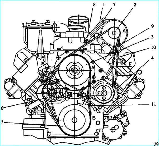
Diagram of checking the belt tension for engines with a fluid coupling: 1 - generator bar; 2 - generator pulley; 3 - fluid coupling pulley; 4 - water pump pulley; 5 - crankshaft pulley; 6 - tensioner roller; 7, 8 - generator bar mounting bolts; 9 generator mounting nut; 10 generator and water pump drive belt; 11 fluid coupling drive belt. When applying a force F = (44.1 ± 5) N (4.5 ± 0.5) kgf) to the middle of the "AB" branch of the belt, the deflection "L" should be 6-10 mm.
Adjusting the tension of the poly V-belt for engines with a fan located above the crankshaft axis is shown in Figure 11.
The tension of the fluid coupling drive belt 11 is adjusted by moving the tension roller 6.
Tension the belt 10 of the generator and water pump drive as follows:
- - loosen nut 9 of the generator mount;
- - loosen bolts 7 and 8, generator bar mount;
- - move the generator, tighten the belt;
- - tighten nut 9, bolts 7 and 8.
After adjustment, check the tension:
- - a correctly tensioned belt, when pressed on the middle of the largest branch with a force of 44.1 ± 5 N (4.5 ± 0.5 kgf), should have a deflection of - 6 ... 10 mm.
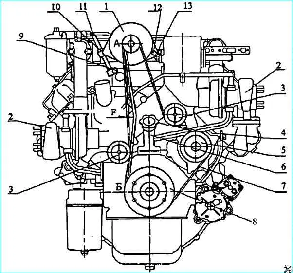
Front view of the 740.30-260 engine (bus version): 1 - generator; 2 - turbocharger; 3 - guide roller; 4 - oil level gauge; 5 - water pump pulley; 6 - oil filler pipe; 7 - poly V-belt; 8 - crankshaft pulley; 9, 13 - bolts; 10, 12 - nuts; 11 tension bolt
Adjust the tension of the poly V-belt for the 740.30-260 engines of the bus assembly (Figure 12) by changing the position of the generator I in the following sequence:
- - loosen bolts 9, 13, lock nut 10 and nut 12;
- - move generator 1 using tension bolt 11;
- - tighten bolt 9, 13, lock nut 10 and nut 12.
After adjustment, check the tension:
- - a correctly tensioned belt when pressing on the middle of the largest branch with a force of 44.1 ± 5 N (4.5 ± 0.5 kgf) must have a deflection of 6...10 mm.
")

")
")
")
")
")
")
")