All devices designed to start automobile engines at subzero ambient temperatures are divided into two types: devices. ensuring the start of a cold engine, and devices that provide it with pre-heating
The first type of device makes it possible to start the engine without first changing its thermal state, the second changes the thermal state of the engine before starting by heating it to a temperature at which reliable starting is possible.
Both types of devices are used on KamAZ engines. As the first one, an electric torch device is used; the second one is a preheater.
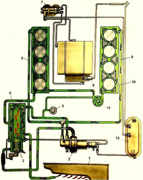
1 - oil pan; 2 - pumping unit; 3 - heater boiler; 4 - liquid supply tube; 5 - filler neck; 6, 9 - tubes for draining liquid from the block to the heater; 7 - fuel filter; 8 - fuel priming pump; 10 - block water jacket; 11 - water pump; 12 - fuel tank
Pre-heater
The pre-heater is a device designed to provide general warming up of the engine before starting at subzero ambient temperatures.
The heater is mounted directly on the car and operates autonomously, regardless of the engine, using only the electricity from the car's batteries.
This is a flame heater (Fig. 1), in which, due to the heat released during the combustion of liquid fuel, the coolant of the engine cooling system is heated.
The coolant, constantly circulating through the heat exchanger of the heater, heats up and transfers heat, releasing it to engine parts.
At the same time, heating of the oil in the oil pan is ensured! exhaust gases.
KamAZ engines use a fluid heater - diesel model PZD-30.
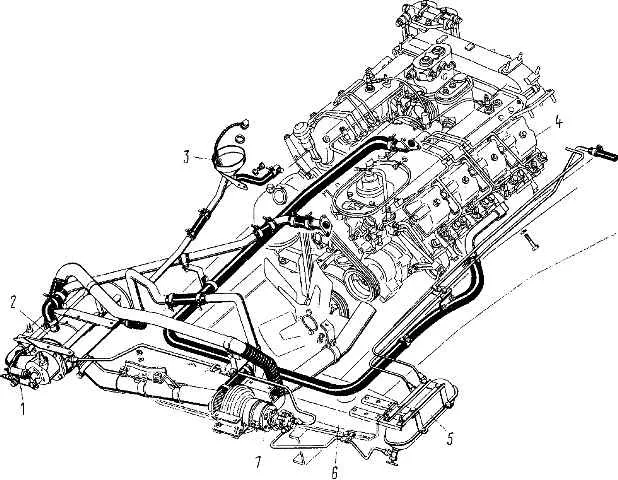
The heater is installed under the front cross member 6 (Fig.) of the car frame and includes a boiler 2 with a burner, an electromagnetic fuel valve 1 with a nozzle and an electric fuel heater, a pump unit 7 with an electric motor, a fan, liquid and fuel pumps, an electric spark ignition system fuel mixture and heater remote control system.
The heater is powered from a special fuel tank 5, which is filled automatically when the engine is running.
When the engine is not running, the tank can be filled with a manual fuel pump installed on the injection pump.
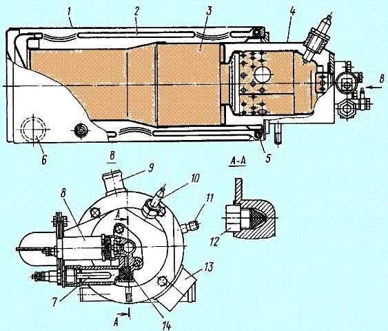
Heat exchanger: 1-heat exchanger: 2 - return gas duct; 3 - straight gas duct; 4 - burner; 5 - gas fuel heater; 6 - liquid supply pipe: 7 - electric fuel heater; 8 - solenoid valve; 9 - pipe for draining liquid from the heat exchanger; 10 - electric spark plug; 11- fitting for supplying fuel to the heater in the heat exchanger; 12 - nozzle; 13 - exhaust gas outlet pipe; 14 - fuel filter
The heater boiler (Fig. 3) is made of stainless steel sheet and is designed to transfer heat to the liquid circulating through it.
According to the principle of operation, the boiler is a recuperative heat exchanger (heat is transferred from combustion products to the coolant through a solid wall separating them) and consists of two liquid jackets and two gas pipes.
Combustion products from the burner are directed into the direct gas duct, then enter through the return gas duct and are discharged from the boiler to the engine crankcase to heat the oil.
A heater is installed at the outlet of the return flue, which heats the fuel supplied to the injector to a temperature of 60-80° C in the exhaust gases.
The burner is removable and secured to the boiler with bolts. This allows you to periodically or as necessary clean the internal surfaces of the burner and boiler flue from carbon deposits.
In the combustion chamber of the burner, in the zone of its mixture formation, a combustible mixture consisting of fuel and air is prepared, ignited and burned.
The air supply to the burner is carried out in a direction perpendicular to its axis. This provides airflow to the end of the injector and the spark plug, reducing carbon formation on their surfaces.
The spark plug (Fig. 4) of the heater differs from a conventional automobile spark plug in the side electrode, the role of which is played by the outer screen 3.
The presence of a screen around the central electrode makes it possible to obtain a spark discharge in any part of the screen circumference, thereby increasing the reliability of the spark plug under operating conditions in an area of increased carbon formation.
The length of the spark plug is selected so that the spark discharge zone is located in the zone of fuel spray by the nozzle.
Npump unit is a device consisting of a fan (supercharger), fuel and liquid pumps driven from one electric motor
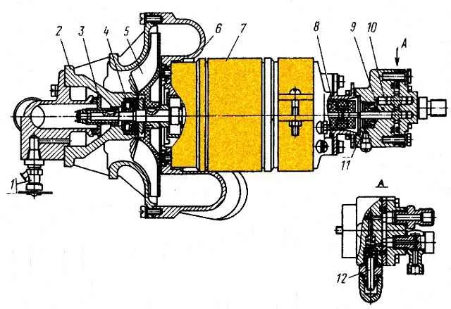
Pumping unit: 1- drain tap; 2 - liquid pump housing; 3 - working wheel of the liquid pump; 4, 11 - sealing cuffs; 5 - fan impeller; 6 - fan housing; 9 - fuel pump drive gear; 10 - fuel pump driven gear; 12 - pressure reducing valve
Die-cast aluminum fluid pump and fan mounted on one side of the drive motor
The fuel pump, which has a self-contained housing, is mounted on the opposite side of the electric motor
This design of the pump unit does not cause difficulties during installation and is convenient to maintain
Centrifugal-type liquid pump is designed to circulate fluid between the preheater and the engine cooling system
The impeller is installed on the electric motor shaft and secured with a nut.
On the fan side, the working cavity of the pump is sealed with a rubber cuff.
Liquid is supplied to the pump through a pipe on the pump cover, and discharged through a pipe on the pump body. A faucet is used to drain liquid from the pump cavity
A centrifugal fan provides air supply to the heater burner.
The fan impeller is mounted on the motor shaft on a key and secured with a nut.
The required clearance between the impeller and the fan housing is ensured by a spacer sleeve installed between the electric motor bearing and the impeller hub.
The gear-type fuel pump supplies fuel under pressure to the heater nozzle.
The pump shaft on the electric motor side is sealed with a rubber cuff. The pump drive gear shaft is connected to the electric motor shaft by an elastic coupling.
The supply of the fuel pump is regulated by a pressure reducing valve, which ensures that fuel is bypassed from the discharge cavity of the pump to the suction cavity.
The electric spark ignition system is designed to provide a spark discharge in the burner when starting the heater.
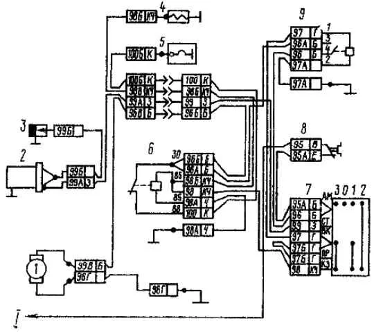
Electrical diagram of the preheater system: 1 - pump electric motor; 2 - pre-heater ignition coil with switch; 3 - spark plug; 4 - solenoid valve; 5 - fuel heater; 6 - heater relay; 7 - preheater control switch; 8 - fuse 30 A; 9 - contactor; I - to fuse
The fuel mixture in the heater burner is ignited by a high-voltage discharge, which is formed between the electrodes of spark plug 3.
High voltage on the spark plug electrodes is created by a transistor switch with induction coil 2.
The heater remote control system makes it possible to control the operation of the heater, both when the vehicle's cab is in working position and when the cab is raised.
Switch 7 for controlling the operation of the heater, mounted on a bracket in the cabin, has four possible positions:
- - position 0 - everything is off;
- - position I - the electric motor of the pump unit, the solenoid valve and the spark plug are turned on;
- - position II - the electric motor of the pump unit and the solenoid valve are turned on;
- - position III - the electric motor of the pump unit and the electric motor of the fuel are turned on.
The heater works as follows. The heater fuel pump takes fuel from the tank, which is supplied to the nozzle through an open solenoid valve and injected into the internal cavity of the burner.
The atomized fuel is mixed with the air supplied by the fan, ignites and burns, heating coolant exchanger.
Fuel combustion products are directed through the exhaust pipe under the engine oil sump and heat the oil in it.
At service C (autumn):
- - clean the spark plug from carbon deposits;
- - wash the fuel pump pressure reducing valve;
- - check the operation of the preheater.
When checking the operation of the preheater, do not allow coolant and fuel to leak in the pipeline connections and taps.
Normal operation is determined by the uniform hum of combustion in the heat exchanger and the release of exhaust gases without smoke or open flame.
If necessary, adjust the fuel flow using the fuel pump pressure reducing valve in the following order:
- - unscrew the cap nut on the fuel pump;
- - loosen the lock nut of the adjusting screw;
- - by turning the adjusting screw to the right (fuel supply increases) or to the left (fuel supply decreases), adjust the heater operating mode.
After completing the adjustment, lock the adjusting screw with the locknut and screw on the cap nut.
To ensure normal operation of the heater, the fuel supply should be regulated at negative ambient temperatures (not higher than minus 5ºС).
After washing the car and fording in the cold season, remove the water that has entered the air tract of the fan by turning on the pump unit for 3-4 minutes; to do this, move the switch knob to position III, having previously disconnected the wire of the electric fuel heater.
Some vehicles are equipped with pre-heater 15.8106 - Pre-heater 15.8106 for Kamaz engine