The pre-heater is designed to warm up a cold engine and automatically maintain the thermal state of the engine and cabin, regardless of the operation of the diesel engine
The heater is operated at an ambient temperature from minus 50° C to plus 65° C with a relative humidity of up to 80% at a temperature of 15° C.
Safety requirements
- When using the heater, remember that violation of the heater operating rules or its malfunctions can cause a fire.
- Using the heater with an unfilled engine cooling system is strictly prohibited.
- It is prohibited to turn on the heater without fuel.
- It is prohibited to turn off the heater before the end of the purge cycle by breaking the fan motor circuit.
- When It is prohibited to open the burner when the heater is operating.
- The burner may only be opened after the heater has been disconnected from the power supply and the purge cycle has been completed, as indicated by the pump and fan motors stopping. When closing the burner, the nuts on the hinged bolts must be securely tightened.
- If you frequently drive on dirty roads, it is necessary to regularly clean the combustion air intake and exhaust gas outlet pipes. In summer, it is advisable to close the air intake system.
- The heater must be switched off at the places where the vehicle is refueled.
- When performing electric welding work on the vehicle, it is necessary to disconnect the six-plug connector on the heater control unit (to protect the electronic control unit).
- The "minus" of the heater power supply must be directly connected to the negative terminal of the battery, but not through the "ground" switch.
- It is prohibited to operate the heater with malfunctions that cause a fire hazard.
- A vehicle equipped with a heater must have a fire extinguisher.
- It is prohibited to operate the heater in closed, unventilated areas.
- After finishing work, close the fuel valve.
Technical specifications heater
- Model: 15.8106-01
- Heat output: 11.6 (10000) kW (kcal/h)
- Fuel: Diesel
- Fuel consumption, kg/h: 1.25
- Nominal voltage, V: 24
- Working voltage, V: 20-30
- Power consumption (without pump), W: 70
- Pump: electric circulation mod.35.3730
- Pump capacity at back pressure of 0.015 MPa, l/h, not less than: 1600
- Nominal voltage, V: 24
- Power consumption, W, not more than: 46
The heater is installed on the front cross member of the frame and consists of a heat exchanger 19 (Fig. 1) and a folding burner.
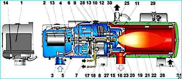
Pre-starting heater: 1 - control unit; 2 - DC motor; 3 - suction pipe; 4 - coupling: 5 - fan: 6 - bearing; 7 - gear; 8 - fuel pump; 9 - electromagnetic valve; 10 - injector body; 11 - injector; 12 ignition electrode; 13 - electrode holder; 14 bypass valve; 15 - flame indicator: 16 disk; 17 - fuel supply pipe; 18 - fuel outlet pipe; 19 - heat exchanger: 20 - swirler; 21, 22 - heat exchanger pipes; 23 - exhaust gas outlet pipe; 24 - "inlet" pipe; 25 - "outlet" pipe; 26, 27 - heater brackets; 28 - high-voltage power source; 29 - thermal fuse: 30, 31 - sensors for heater operation control
Welded heat exchanger with a "jacket" inside which the heated liquid - coolant - circulates. A combustion chamber with a swirl element 20 is inserted inside the heat exchanger.
Nipples 24, 25 for the inlet and outlet of the heated liquid, and pipe 23 for the outlet of exhaust gases are welded to the outer pipe of the heat exchanger.
A thermal fuse 29 and temperature sensors 30 and 31 are installed on the heat exchanger under the casing, which monitor the temperature of the liquid in the heater system and the vehicle cabin.
Sensor 30 monitors the liquid temperature from (48±5)°C to (70±3)°C, sensor 31 - from (40±3)°C to (30±5)°C (maintains the thermal regime in the vehicle cabin).
The thermal fuse switches off the heater when the maximum permissible liquid temperature in the heat exchanger is reached (103±5)°C (when leaving the sensor 30 failure, lack of water in the system, etc.).
The burner consists of a fan 5, a fuel pump 8, a nozzle 11, an electromagnetic valve 9, a flame indicator 15 and two ignition electrodes 12.
The burner serves to create a torch and provide the necessary thermal conditions for the heated environment.
Valve tor with a plastic impeller and a DC electric motor 2 is designed to create an air flow.
The fuel pump 8 is gear-type and is designed to supply fuel to the injector under pressure.
The pump is driven by an electric motor 2 through a gear transmission 7. The injector 11 sprays the supplied fuel.
A sintered bronze filter is installed in front of the sprayer to increase the reliability of the injector.
The electromagnetic valve 9 controls the fuel supply from the fuel pump to the injector on command from the control unit, depending on the operating modes of the heater.
The flame indicator 15 is mounted on the disk 16 in close proximity to the injector and flame and sends commands to the high-voltage source, turning it on and off.
Two ignition electrodes 12 are located in front of the injector and provide ignition of the heater due to a spark between them, formed when high voltage is supplied from the power source 28.
The burner is secured to the heat exchanger with hinged bolts and provides access to its elements during installation and maintenance.
Wiring diagram of the heater to the cabin heating and engine cooling system with a plastic casing, on which the high-voltage source 28 and the suction pipe 3 for air intake are fixed.
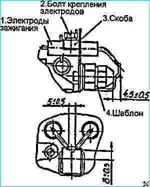
The ignition electrodes are installed according to the template, as shown in Fig. 2
The circulation pump is installed on the front crossmember and is designed to pump coolant through the heater.
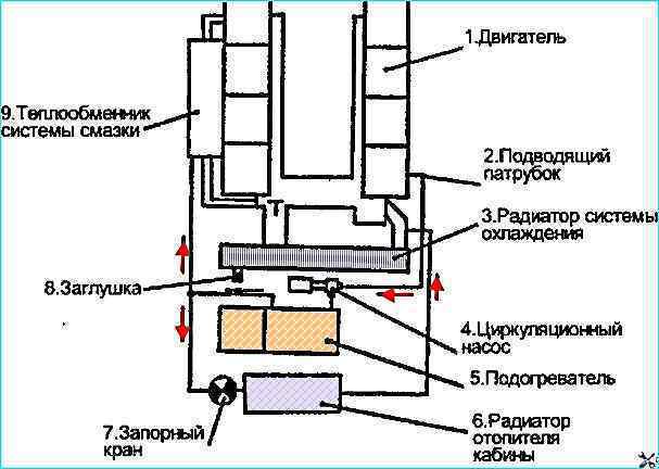
The heater connection diagram to the engine cooling and cabin heating system (see Fig. 3) allows for optimal use of the heater's thermal energy by creating various coolant circulation circuits.
When the heater is operating, the fuel is supplied to the injector under pressure by the pump. Excess fuel from the fuel pump goes back to the heater tank.
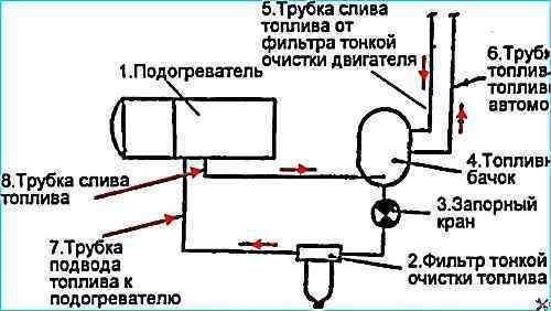
The fuel supply diagram of the heater is shown in Figure 4
Heater operation
The electric circuit for controlling the heater is shown in Figure 5 of the same name.
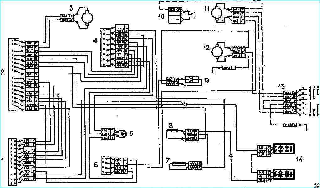
Electrical circuit of the heater: 1 heater boiler; 2 - control unit; 3 - pump electric motor; 4 - timer; 5 - PTO indicator; 6 - thermostat; 7, 8, 10 - 10A fuses; 9 - diode with protective housing; 11, 12 - heater electric motors; 13 - heater electric motor switch; 14 - storage batteries
A temperature sensor installed on the heat exchanger is used to regulate the temperature of the liquid in the system.
An electronic timer is used to control the heater.
The front panel of the timer contains:
- - timer controls - buttons "RESET", "HEATING", "TIMER", "MINUTES", "HOURS", "INDICATION";
- - digital display;
- - indicators "HEATING" (green), "TIMER " (red);
- - indicator "NOZZLE HEATING" - a red dot in the lower right corner of the digital display.
Timer operation procedure:
- - the timer is pre-set to its initial state by pressing the button "RESET";
- - on the digital display of the timer, using the "HOURS" and "MINUTES" buttons, a number is set equal to the time interval (up to 23 hours 59 minutes), after which the timer should turn on the heater.
The timer is started by pressing the "TIMER" button, i.e. the moment this button is pressed is the beginning of the countdown of the set time interval;
- - after starting, the timer will turn on the injector heater for (90+30) s (to heat the injector) after the time interval set on the display, and then will issue a signal to turn on the heater, the duration of this signal is (64+10) min.
At this point, the timer completes its operating cycle, stops counting down, the digital display saves the value of the time interval and the value of the counted time.
The timer has a mode for immediate switching on of the heater (immediate signal to turn on the heater), which is carried out by pressing the "HEATING" button - in this case, the timer issues a signal to turn on the heater regardless of what mode it was in before.
Switching off heater in this case is carried out by pressing the "RESET" button.
Operation of the indicators:
- - "HEATING" - lights up when the heater starts working and goes out when the heater is turned off;
- - "INJECTOR HEATING" - lights up for the duration of the injector warming up;
- - "TIMER" - starts blinking when the "TIMER" button is pressed (that is, when the timer starts): blinking of the indicator means that the timer is counting down the time interval set on the display.
When the timer gives a signal to turn on the heater, the indicator stops blinking - it lights up constantly during the entire time the heater is working. If one of the timer indicators does not work, press the "RESET" button. Determine the cause of the failure.
Operation of the digital display:
- - when the timer is initially connected to the vehicle's on-board network, the digital display turns on for (10+5) s and goes out;
- - the display turns on when the "INDICATION" button is pressed and automatically turns off (goes out) (10+5) s after this button is released;
- - the "INDICATION" button also simultaneously switches the digital display to one of the operating modes: "COUNTDOWN" and "INTERVAL" (the corresponding marking is applied to the front panel).
"COUNTDOWN" mode - the "INDICATION" button is pressed, the display shows the time elapsed since the timer was started.
"INTERVAL" mode - the button "INDICATION" is released, the display shows the set time interval;
- - setting the time interval after which the timer should turn on the heater on the digital display is performed in the following sequence: the "RESET" button is pressed, using the "HOURS" and "MINUTES" buttons (pressing them turns on the display, lowering them turns off) set the time interval.
By pressing the "RESET" button, the timer returns to its initial state from any mode.
Switching on:
Open the fuel valve of the heater.
The heater is switched on using the timer (at a preset time or immediately).
After the injector has warmed up, if the temperature sensor contacts are closed (that is, if the liquid temperature is below the set limit), the electric motors of the circulation pump and fan and the control lamp built into the switch lights up.
After about 20 seconds, the high-voltage power source and the fuel solenoid valve are automatically turned on.
A spark appears between the electrodes, the fuel ignites, after which, if combustion is stable, the high-voltage source is turned off by the flame indicator signal.
Combustion will continue until the liquid temperature reaches the set value, after which the sensor contacts open, and the fuel solenoid valve is de-energized, the fuel supply and combustion stop.
For 150 seconds, both electric motors will continue to operate, after this time the fan motor will turn off, then only the circulation pump motor will operate, the control lamp continues to light.
When the liquid temperature drops below the set limit, the sensor contacts will close and the heater will ignite, as shown above.
If the temperature sensor contacts are open when the heater is turned on (the liquid temperature is above the set limit), only the pump electric motor will turn on and the control lamp will light.
The heater will ignite when the liquid temperature drops below the set limit (see above).
Operating mode (if ignition does not occur or combustion has stopped):
If ignition does not occur when the heater is turned on or when the temperature sensor contacts are closed during liquid temperature regulation (for example, due to lack of fuel, due to open contacts of the thermal fuse (on the heat exchanger), 10 seconds after the high-voltage power source and the valve are turned on, they will automatically turn off, while the lamp will go out, and after 150 seconds the electric motor will turn off pump and fan (complete shutdown of the heater).
If the flame fails, the high-voltage source is switched on for 10 s and if ignition does not occur, the heater is switched off in the order described above.
To switch the heater on again, it is necessary to switch it off by pressing the "RESET" button, and then switch it on again by pressing the "HEATING" button of the timer.
Switching off:
To switch off the heater, it is necessary to press the "RESET" button of the timer. At the same time, the control lamp will go out and the fuel valve will turn off (burning stops), and after 150 s the electric motors of the pump and fan will turn off (complete shutdown of the heater).
Close the fuel valve of the heater supply.
Emergency modes
If the liquid temperature exceeds 103±5°C, which is possible in the event of a temperature sensor failure, the contacts of the thermal fuse will open. In this case, the fuel valve is switched off and combustion stops.
It is necessary to determine and eliminate the cause of the defect and only after this and the thermal fuse has cooled down to a temperature of approximately plus 30°C, close its contacts by pressing the button located on the thermal fuse housing and turn on the heater again with the switch.
If the control lamp goes out when switched on, this indicates a heater malfunction.
When switching on the heater, the following locks for switching it on are provided:
- - the supply voltage in the circuit is below 18 V: the control lamp will light and the pump and fan electric motors will turn on, after 10 seconds the lamp will go out, and after 150 seconds the electric motors will turn off (ignition will not occur);
- - the pump electric motor circuit is open: the fan electric motor will turn on, the control lamp will not light and after 150 s the fan motor will switch off (ignition will not occur);
- - the contacts of the thermal fuse are open (in the power supply circuit of the fuel valve winding): the electric motors turn on and the lamp lights up, after 20 s the high-voltage source will turn on, but due to the lack of power, the valve will not turn on and ignition will not occur.
After 10 s of operation, the high-voltage source will switch off.
When using the heater, it should be taken into account that if the heater is forced off or if ignition fails, the control lamp will go out immediately and combustion will stop, however, the pump and fan electric motors will switch off only after 150 s, which ensures cooling of the burner and swirler.
During this time, you must not try to de-energize the heater (for example, by disconnecting the block of the heater wire bundle, since this will lead to an increase in the temperature inside heater, which can cause, in particular, burning of the electrical wires inside the heater, failure of the flame indicator and warping of the swirl).
Operation in the mode of automatic maintenance of the thermal state of the cabin
To operate in the mode of automatic maintenance of the thermal state of the cabin, it is necessary to turn on the battery switch, the ignition switch and the switch of the electric motors of the cabin heater to a low speed.
When using the heater, the electric motors of the standard cabin heater can be turned on and off in addition to the autonomous control of the standard key switch.
A temperature sensor is used to control the switching on of the electric motors of the heater, the contacts of which close when the liquid temperature in the system is plus 40 ° C.
The specified sensor is installed on the heat exchanger of the heater, and its contacts are included in the circuit of the thermostat with a built-in relay.
The electric motors of the heater do not turn on immediately when the heater is turned on, but only after the temperature sensor contacts are closed (plus 40°C) and with the instrument and starter switches on.
The thermostat will turn the heater electric motors on and off depending on the air temperature in the cabin. The operation of the heater itself does not depend on the state of the contacts of this temperature sensor and thermostat.
Possible malfunctions of the pre-heater 15.8106, and methods for eliminating them
Malfunction
- Reason
Remedy
The heater does not start
- No voltage in the heater power supply circuit
Check the fuses, electrical wires, polarity of the connection
- The collector or brushes of the fan motor are faulty
Replace the electric motor or brushes
- Open circuit of the circulation pump electric motor
Check the operation of the pump by connecting it directly to the battery
No ignition, the control unit automatically turns off
- Lack of fuel
Fill with fuel
- Fuel has frozen in the lines (at low temperature)
Fill with recommended fuel. Blow out the lines, clean the filter
- Fuel pump does not supply fuel
Check the drive, replace pump
- Solenoid valve does not open
Check the electrical connections of the valve, replace the solenoid valve. Check the thermal fuse (press its button)
- The injector is clogged
Clean the fuel filter, replace the injector nozzle
- No ignition voltage
Check the electrical wires and plug connections.
Replace the control unit.
Replace the high-voltage source
- Leaky pipes (the pump sucks in air)
Tighten the fuel pipe connections
- Incorrectly installed ignition electrodes
Adjust the gaps between the electrodes and the injector
- Too much combustion air
Adjust the air supply with the air intake flap
The heater does not provide high-quality combustion
- Excess fuel, bad nozzle atomizer, nozzle clogged (fuel is supplied at an angle)
Clean the nozzle, replace the nozzle atomizer
Soot forms on the exhaust
- Insufficient air for combustion, the heater smokes “thickly”
Clean the air intake pipe. Adjust the air intake flap position, the gap between the impeller and the fan housing
- Poor air atomization
Adjust the pump bypass valve pressure
- Low fan motor speed (low motor voltage or worn brushes) and engine damage
Remove low voltage, replace brushes, replace the motor
- The exhaust pipe is bent or displaced, clogged with soot, dirt
Repair or clean the exhaust pipe. Clean the heat exchanger (combustion pipe and inner pipe of the heat exchanger)
Blue smoke is formed
- Lack of fuel. The nozzle or filter is clogged
Clean or replace the nozzle. Clean the filter
- Too much combustion air
Adjust the air intake flap
The heater switches off from the thermal fuse
- Insufficient coolant in the cooling system
Fill the coolant circulation system and eliminate air locks
- Remote thermostat is faulty
Replace the thermostat
- No or low coolant circulation
Check the correct connection of the liquid and the serviceability of the circulation pump
The heating capacity of the heater is insufficient
- Soot in the combustion chamber and heat exchanger
Clean the combustion chamber and heat exchanger
- There is scale
Remove scale
The heater makes a lot of noise when operating
The fan impeller is touching the housing.
Adjust the gap between the housing and the impeller and secure it.
- The fuel pump is faulty
Replace the pump
")

")
")
")
")
")
")
")