Adjusting the tension of the generator drive belts and water pump of the YaMZ-236M2, YaMZ-238M2 engines
Tools and accessories will be required: a 13 and 17 wrench, a mounting blade and a device for checking the tension of drive belts, a 17 socket wrench
Protect the belts from oil and fuel, monitor their tension and, if necessary, adjust it.
Check the belt tension especially carefully during the first 50 hours of engine operation, since at this time they are most stretched.
Belt tension should always be normal, since excessive and insufficient tension leads to premature failure.
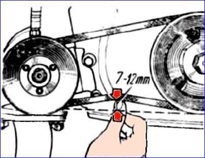
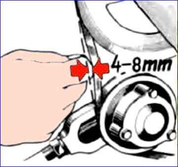
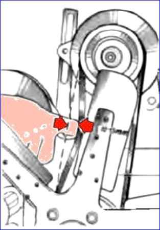
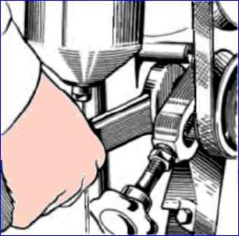
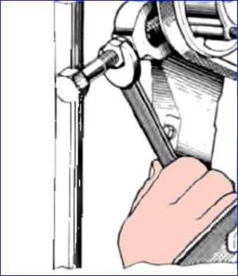
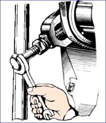
Normally tensioned belts, when pressed on the middle of the branch with a force of 40 N (4 kgf), should bend: the water pump belt - by 7-12 mm (Fig. 1), the compressor belt - by 4-6 mm on a short branch (Fig. 2), generator drive belts - by 10-15 mm (Fig. 3).
If the belts bend more or less than specified, adjust their tension.
It is recommended to check the belt tension using a device like KI-8920.
Adjust the tension of the water pump belt using shims.
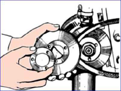
To tension the belt, unscrew the nuts securing the side of the pulley and remove one or two adjusting shims (Fig. 4).
Place the spacers on the outer side of the sidewall and tighten the nuts sequentially, in several steps, turning the pulley after tightening each nut.
Then check that the belt tension is correct.
When replacing an old belt with a new one, place all the spacers between the hub and the removable sidewall of the pulley and adjust the belt tension as indicated above.
Adjust the compressor belt tension using a tensioner.
Before adjustment, unscrew the lock nut by one turn, the nut securing the tensioner pulley axis (Fig. 5) by half a turn, and the tensioner bolt nut (Fig. 6) by two turns.
Rotate the tensioner bolt (Fig. 7) to adjust the belt tension.
After adjustment, tighten the nut and locknut of the axle fastening to a torque of 120-150 Nm (12-15 kgf-m) and the tensioner bolt nut to a torque of 10-20 Nm (1-2 kgf-m).
If the tightening torque is higher, the adjustment will be disrupted due to movement of the pulley axis.
The tension of the generator belts can be adjusted by moving the generator relative to the axis of its mounting.
Before adjustment, loosen the generator mounting bolts, the generator mounting nut and the generator mounting bolt to the mounting bracket.
After adjustment, securely secure the generator.
If the stretch is increased or at least one of the generator drive belts is broken, replace both belts as a set to ensure an even load on them.
Adjustment and tension of generator and water pump drive belts of KAMAZ-740.11-240, -740.13-260, -740.14-300 engines
Removing the belts
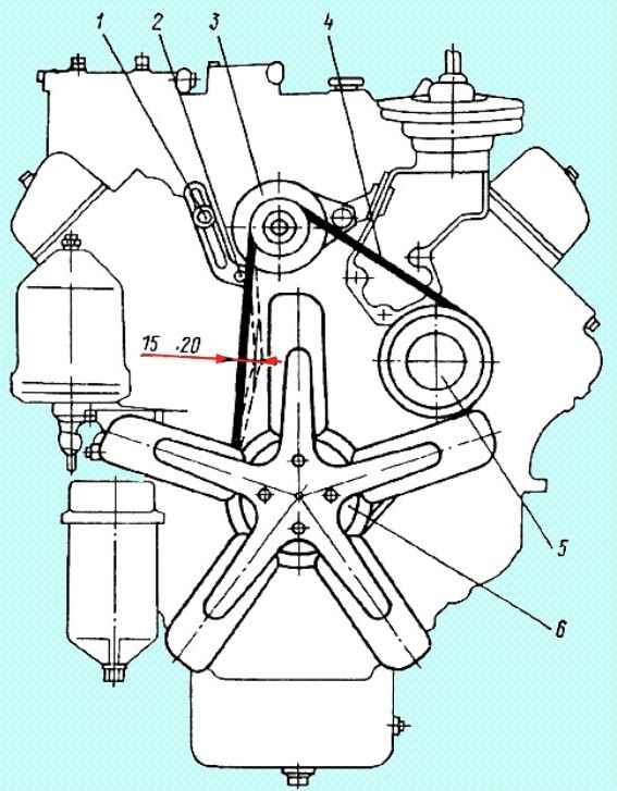
Using a 17mm wrench and a 17mm spanner, loosen the nuts securing the front and rear generator supports
Loosen bolt 1 (Fig.) securing the bar and bolt 2 securing the bar to the generator
Turning the generator down, remove the belts from pulleys 3, 5 and 6
Installing belts
Installing belts in the grooves of pulleys 3, 5 and 6
Moving the generator up, using a mounting spatula, tighten bolts 1 and 2 securing the generator bar
A correctly tensioned belt, when pressed on the middle of the largest branch with a force of 39.2 N (4 kgf), should have a deflection of 15-22 mm
Tighten the nuts securing the front and rear generator supports.
Adjustment and tension of generator and water pump drive belts of KAMAZ-740.30-260 (740.30-3902001RE) engines
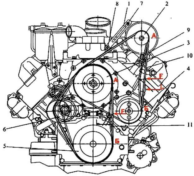
Adjusting the tension of the poly V-belt for engines with a fan located above the axis of the crankshaft is shown in Figure 9
The tension of the hydraulic coupling drive belt 11 is adjusted by moving the tension roller 6
Tension of the generator and water pump drive belt 10 is performed as follows:
- - loosen nut 9 securing the generator;
- - loosen bolts 7 and 8, securing the generator strip;
- - moving the generator, tighten the belt;
- - tighten nut 9, bolts 7 and 8
After adjustment, check the tension:
- - a correctly tensioned belt when pressed on the middle of the largest branch with a force of 44.1±5 N (4.5±0.5 kgf) should have a deflection of 6-10 mm.
When applying force F = (44.1±5) N ((4.5±0.5) kgf) to the middle of the belt branch “A-B”, the deflection value “L” should be 6-10 mm (Figure 9)
Adjustment and tension of generator and water pump drive belts of KAMAZ-740.30-260 bus engines
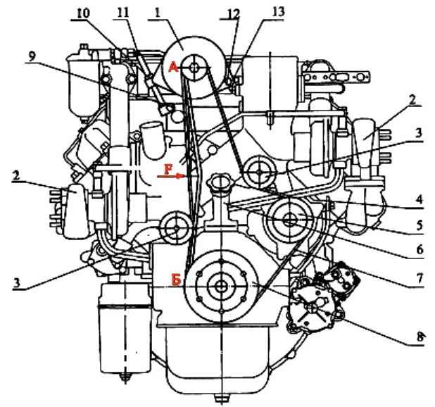
Adjustment is carried out by changing the position of generator 1 (Fig. 10) in the following sequence:
- - loosen bolts 9, 13, lock nut 10 and nut 12;
- - move generator 1 using tension bolt 11;
- - tighten bolt 9, 13, lock nut 10 and nut 12
After adjustment, check the tension:
- - a correctly tensioned belt when pressed on the middle of the largest branch with a force of 44.1±5 N (4.5±0.5 kgf) should have a deflection of 6-10 mm
Adjusting and tensioning the drive belts of the generator and water pump of the KAMAZ-740.50-360, -740.51-320 engines
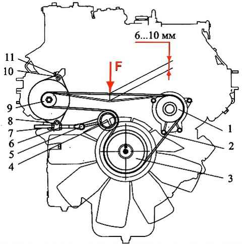
Adjusting the tension of poly V-belt 2 (Figure 11) of the generator and water pump drive for engines with a fan located along the axis of the crankshaft is carried out as follows:
- - loosen bolt 11 fastening the rear leg of the generator, nut 10 fastening the front leg of the generator, bolt 8 fastening the generator bar, bolt 5 fastening the tension bolt;
- - by moving nut 6 we ensure the necessary belt tension and use nut 7 to fix the position of the generator;
- - tighten bolts 5, 8 and 11 and tighten nut 10
After adjustment, check the tension:
- - a correctly tensioned belt 2, when pressed on the middle of the largest branch with a force of 44.1±5 N (4.5±0.5 kgf), should have a deflection of 6-10 mm
")

")
")
")
")
")
")
")