Crank mechanism of KAMAZ engines 740.11-240, 740.13-260, 740.14-300, 740.11-3902007 RE:
The crankshaft is made of high-quality steel and has five main and four connecting rod journals, hardened by high-frequency current, which are connected to each other by cheeks and mated with them by transition fillets
For uniform alternation of working strokes, the location of the connecting rod journals of the crankshaft is made at an angle of 90°.
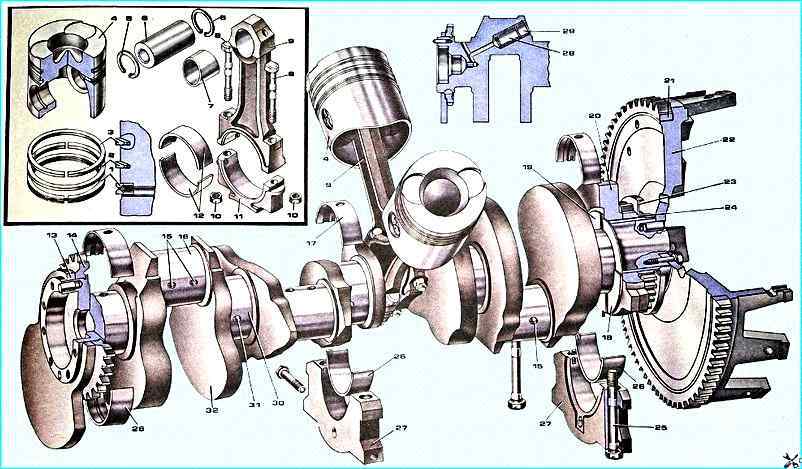
Crank mechanism: 1 - oil scraper piston ring; 2, 3 - compression piston rings; 4 - piston; 6 - piston pin; 7 - connecting rod upper head bushing; 8 - connecting rod cap bolt; 9 - connecting rod; 10 - nut; 11 - connecting rod cap; 12 - connecting rod lower head liners; 13 - front counterweight; 14 - oil pump drive pinion; 15 connecting rod bearing lubrication channels; 16 crankshaft connecting rod journal; 17 upper bearing shell; 18 - lower half ring of thrust bearing; 19 - upper half ring of thrust bearing; 20 - rear counterweight; 21 - flywheel ring gear; 22 - flywheel 23 - rear oil deflector; 24 - timing gear; 25 - main bearing cap bolt; 26 - lower bearing shell; 27 - main bearing cap; 28 - bushing; 29 - plug; 30 - crankshaft main journal; 31 - main bearing lubrication channel; 32 - crankshaft
Two connecting rods are attached to each crankpin: one for the right and one for the left row of cylinders.
Oil is supplied to the crankpins from holes in the main journals through straight holes.
To balance the inertial forces and reduce vibrations, the crankshaft has six counterweights stamped together with the crankshaft cheeks.
In addition to the main counterweights, there are two additional removable counterweights and, pressed onto the shaft, while their angular position relative to the crankshaft is determined by keys.
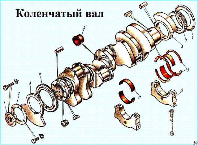
Crankshaft: 1 - power take-off half coupling; 2 - crankshaft nose lock washer; 3 - front counterweight; 4 - oil pump drive pinion; 5 - plug; 6 - rear oil deflector; 7 - timing gear; 8 - rear counterweight; 9 - crankshaft thrust bearing half rings; 10 - crankshaft main bearing cap; 11 - crankshaft main bearing shell
A ball bearing is pressed into the bore of the crankshaft tailstock.
A jet 8 is screwed into the cavity of the front nose of the crankshaft. Through the calibrated hole of which the splined shaft of the power take-off is lubricated to the fluid coupling drive.
The crankshaft is secured from axial movements by two upper half rings and two lower half rings installed in the grooves of the rear main bearing of the cylinder block, so that the side with the grooves is adjacent to the thrust ends of the shaft.
The oil pump drive gear and the leading gear of the camshaft drive are installed on the front and rear noses of the crankshaft.
The rear end of the crankshaft has eight threaded holes for mounting bolts flywheel, the front nose of the crankshaft has eight holes for mounting the torsional vibration damper.
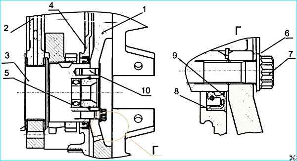
Installing the flywheel and crankshaft seal: 1 - flywheel; 2 - cylinder block; 3 - crankshaft; 4 - flywheel housing; 5 - gearbox input shaft bearing; 6 - washer; 7 - flywheel mounting bolt; 8 - crankshaft seal seal; 9 - seal boot; 10 - flywheel mounting pin
The crankshaft is sealed with a rubber cuff 8 (Fig. 3), with an additional sealing element - a boot 9.
The cuff is located in the flywheel housing 4.
The cuff is made of fluororubber using the technology of molding the working sealing edge directly in the mold.
Diameters of the crankshaft journals:
- - main 95±0.011 mm;
- - connecting rod 80±0.0095 mm.
Eight repair sizes of liners are provided for engine restoration.
Liners 7405.1005170 P0. 7405.1005171 P0. 7405.1005058 P0 are used when rebuilding an engine without grinding the crankshaft.
If necessary, the crankshaft journals are polished.
Tolerances for the diameters of the crankshaft journals, holes in the cylinder block and holes in the lower connecting rod head during engine repair must be the same as the nominal dimensions of new engines.
The main and connecting rod bearings are made of steel tape coated with a 0.3 mm thick layer of lead bronze, a 0.022 mm thick layer of lead-tin alloy and a 0.003 mm thick layer of tin.
The upper and lower main bearing shells are not interchangeable.
The upper shell has a hole for oil supply and a groove for its distribution.
Both shells 4 of the lower connecting rod head are interchangeable.
The shells are secured from rotation and lateral displacement by protrusions (whiskers) entering the grooves provided in the block beds, bearing caps and in the beds connecting rod.
The bearings have design differences aimed at increasing their performance when forcing the engine with turbocharging, while the marking of the bearings has been changed to 7405.1004058 (connecting rod), 7405.1005170 and 7405.1005171 (main).
Therefore, when carrying out repair maintenance, it is not recommended to replace the bearings with serial ones marked 740.100.., since this will significantly reduce the engine life.
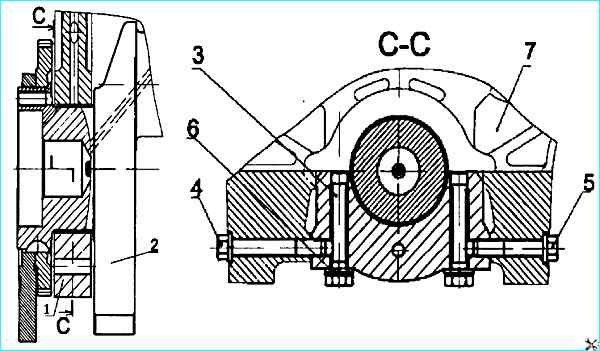
The main bearing caps (Fig. 4) are made of high-strength cast iron grade VCh50.
The caps are fastened with vertical and horizontal tie bolts 3, 4, 5, which are tightened according to a specific pattern with a specified torque.
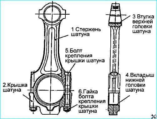
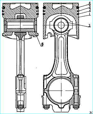
The connecting rod (Fig. 5) is steel, forged, rod I has an I-section.
The upper head of the connecting rod is non-separable, the lower one is made with a straight and flat connector.
The connecting rod is finally machined together with the cover 2. Therefore, the connecting rod caps are not interchangeable.
A steel-bronze bushing 3 is pressed into the upper head of the connecting rod, and replaceable liners 4 are installed in the lower one.
The cover of the lower head of the connecting rod is fastened with nuts 6, screwed onto bolts 5. pre-pressed into the connecting rod rod.
Tightening of the connecting rod bolts is carried out according to the diagram.
On The connecting rod cap and rod are marked with pairing marks - three-digit serial numbers.
In addition, the cylinder serial number is stamped on the connecting rod cap.
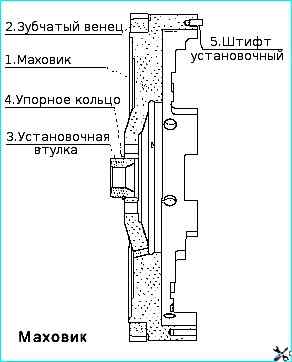
Flywheel 1 (Fig. 6) is secured with eight bolts 7 (Fig. 3) made of alloy steel with a twelve-sided head, on the rear end of the crankshaft and is precisely fixed with two pins 10 and a locating sleeve 3 (Fig. 6).
In order to prevent damage to the flywheel surface, a washer 6 (Fig. 3) is installed under the bolt heads.
A toothed ring 2 is pressed onto the machined cylindrical surface of the flywheel, with which the starter gear engages when the engine is started (Fig. 6).
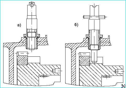
Positions of the flywheel lock handle: a) during operation; b) when adjusting in engagement with the flywheel
When performing adjustment work to set the fuel injection advance angle and the values of thermal clearances in the valves, the flywheel is fixed using a retainer (Fig. 7).
In this case, the design has the following main differences from the serial one:
- - the angle of the groove for the retainer on the outer surface of the flywheel has been changed;
- - the diameter of the bore to accommodate the washer for the flywheel mounting bolts has been increased.
The engines in question can be equipped with different types of clutches.
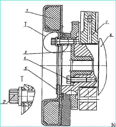
In Fig. 6 flywheel shows a flywheel for a diaphragm clutch.
Installing the crankshaft vibration damper: 1 - damper; 2 - damper mounting bolt; 3 - power take-off half coupling; 4 - half coupling mounting bolt; 5 - washer; 6 - crankshaft 7 - cylinder block
The vibration damper is secured with eight bolts 2 (Fig. 8) on the front nose of the crankshaft.
In order to prevent damage to the surface of the damper housing, a washer 5 is installed under the bolts.
The damper consists of a housing (see Fig. 7) in which the flywheel is installed with a gap.
The damper housing is covered from the outside with a cover. Tightness is ensured by rolling (welding) along the joint of the damper housing and the cover.
There is a high-viscosity silicone fluid between the damper housing and the flywheel, dosed before welding the cover.
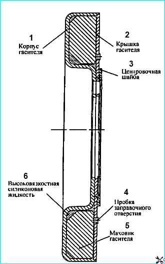
The damper is centered by a washer welded to the housing (Fig. 8).
The torsional vibrations of the crankshaft are damped by braking the damper housing, fixed to the crankshaft nose, relative to the flywheel in a silicone fluid environment.
The braking energy is released as heat.
It is strictly forbidden to deform the damper housing and cover during repair work.
A damper with a deformed housing or cover is not suitable for further use.
Piston 1 (Fig. 9) is cast from aluminum alloy with a wear-resistant cast iron insert under the upper compression ring.
The piston head has a toroidal combustion chamber with a displacer in the central part, it is offset relative to the piston axis away from the recesses for the valves by 5 mm.
The side surface is a complex oval-barrel shape with a lowering in the area of the holes for the piston pin.
The skirt is coated with graphite.
A groove is made in its lower part, which eliminates, if correctly assembled, contact of the piston with the cooling nozzle when at BDC.
The piston is equipped with three rings, two compression and one oil scraper.
Its distinctive feature is the reduced distance from the bottom to the lower end of the upper groove, which is 17 mm.
On engines, in order to ensure fuel efficiency and environmental performance, selective selection of pistons for each cylinder is used by the distance from the axis of the piston pin to the bottom.
According to this parameter, the pistons are divided into four groups 10, 20, 30 and 40. Each subsequent group differs from the previous one by 0.11 mm.
The pistons of the greatest height are supplied as spare parts, therefore, in order to avoid possible contact between them and the cylinder heads in the event of replacement, it is necessary to control the above-piston clearance.
If the clearance between the piston and the cylinder head after tightening the bolts of its fastening is less than 0.87 mm, it is necessary to trim the piston bottom by the missing value size.
The pistons of engines 740.11, 740.13 and 740.14 differ from each other in the shape of the grooves for the upper compression and oil scraper rings.
Installation of pistons from KAMAZ engines 740.10 and 7403.10 is not allowed. It is allowed to install pistons with piston rings of engines 740.13 and 740.14 on engine 740.11.
Compression rings (Fig. Piston with rings assembled with connecting rod) are made of high-strength cast iron, and oil scraper rings are made of gray cast iron.
On engine 740.11, the cross-sectional shape of the compression rings is a one-sided trapezoid, during installation, the inclined end with the “top” mark should be located on the side of the piston bottom.
On engines 740.13 and 740.14, the upper compression ring has a cross-sectional shape of a double-sided trapezoid with a recess on the upper end, which should be located on the side of the piston bottom.
The working surface of the upper compression ring 4 is coated with molybdenum and has a barrel-shaped shape.
The working surface of the second compression ring 5 and oil scraper ring 2 is coated with chrome.
Its shape on the second ring is a cone with a slope towards the lower end, due to this characteristic feature the ring was called "minute".
Minute rings are used to reduce oil consumption per ang ar, their installation in the upper groove is not allowed.
Box-type oil scraper ring with a spring expander having a variable pitch of turns and a ground outer surface.
The middle part of the expander with a smaller pitch of turns when installed on the piston must be located in the ring lock.
On the 740.11 engine, the ring height is 5 mm, and on the 740.13 and 740.14 engines, the ring height is 4 mm.
Installation of piston rings from other KAMAZ engine models may lead to an increase in oil consumption due to burnout.
To exclude the possibility of using non-interchangeable parts of the cylinder-piston group during repair work, it is recommended to use repair kits:
- - 7405.1000128-42 - for the engine 740.11-240;
- - 740.13.1000128 and 740.30-1000128 - for engines 740.13-260 and 740.14-300.
The repair kit includes:
- - piston;
- - piston rings;
- - piston pin;
- - piston pin retaining rings
- - cylinder liner;
- - cylinder liner sealing rings.
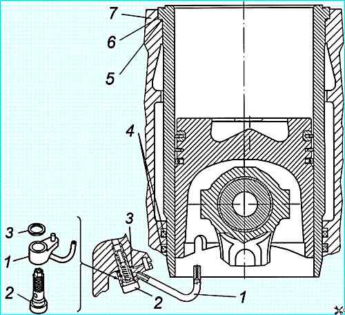
Cylinder liner with piston cooling nozzle: 1 - nozzle tube; 2 - piston cooling nozzle valve assembly; 3 - sealing gasket; 4 - lower liner sealing ring; 5 - upper sealing ring; 6 - cylinder liner; 7 - crankcase
The cooling nozzles (Fig. Installing the liner and the piston cooling nozzle) are installed in the crankcase part of the cylinder block and provide oil supply from the main oil line when the pressure in it reaches 0.8 - 1.2 kg/cm 2 (the valve located in each of the nozzles is adjusted to this pressure) into the internal cavity of the pistons.
When assembling the engine, it is necessary to check the correct position of the nozzle tube relative to the cylinder liner and piston. Contact with the piston is not allowed.
The piston and connecting rod (Fig. 9) are connected by a floating pin 3, its axial movement is limited by retaining rings 6.
The pin is made of chromium-nickel steel, the hole diameter is 22 mm.
Using pins with a 25 mm hole is not allowed, as this disrupts the engine balance.
")

")
")
")
")
")
")
")