The towbar is designed for towing trailers, double-acting, and allows you to soften axial shocks that occur during movement in both directions
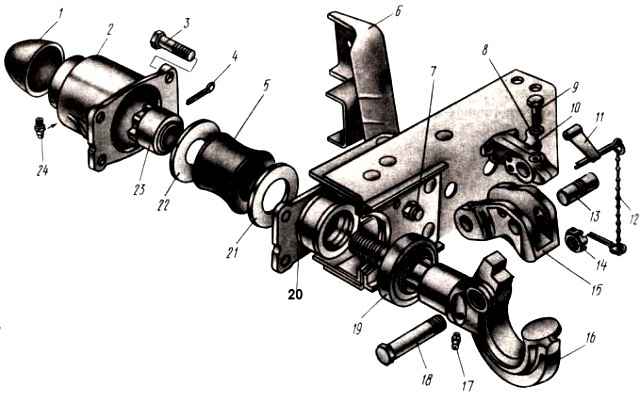
The hook-and-loop towing device of the KamAZ-5320 vehicle (Fig. 1) consists of a hook 16, the shank of which passes through a hole in the rear cross member of the frame.
The stem of the towing hook is inserted into a massive cylindrical housing 2, closed on one side by a protective cap 1, and on the other by a housing cover 20.
Rubber elastic buffer 5 is located between flanges 21 and 22, with the help of which the necessary preload of the rubber buffer is created, softening shock loads when starting a car with a trailer, as well as when driving on uneven roads.
On the pin 18 there is a hook latch 15, locked by a pawl 10, which prevents the trailer drawbar from coming out of engagement with the hook.
The towing device of the KamAZ-53212 vehicle is automatic, of the “pin-and-loop” type, ensuring backlash-free coupling of the tractor with the trailer.
It consists of a V-shaped catcher 1 (Fig.), on which an actuator with a self-release fuse 4 is attached.
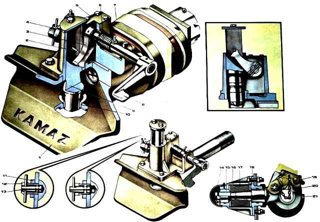
The actuator is a housing 2, in the guide cavity of which the pin 10 moves.
The pin in the upper position is fixed by lever 3, fixed to the axis, on which handle 9 and two coil springs 5 are also fixed.
The device is secured to the rear cross member of the frame 8 with a nut 7.
Rubber buffers 6 are installed on both sides of the frame cross member, providing double-sided shock absorption.
To couple a vehicle with a trailer, you must do the following:
- - brake the trailer with a parking brake;
- - remove the self-assessment fuse from engagement with the pin 10 and fix it in this position by turning it clockwise;
- - turn the handle 9 of the towbar up, while the lever 3 raises the kingpin 10 and locks it in this position (Fig. 2);
- - install the trailer drawbar so that the coupling loop is at the level of the catcher 1 of the towbar;
- - move the car back so that the coupling loop of the trailer drawbar enters the catcher of the towbar.
At the same time, it will hit the lower conical surface of the king pin; from the impact, the king pin should go down all the way, and the self-release safety device should enter the pin socket.
Fifth wheel coupling
It is designed for towing a semi-trailer with a truck tractor; it provides semi-automatic coupling and uncoupling of the tractor with a semi-trailer.
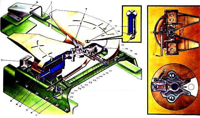
The fifth wheel is mounted on brackets 3 (Fig. 3) of the coupling device, which are bolted to the car frame.
Two saddle brackets 26 with rubber-metal hinges are attached to these brackets.
The saddle is mounted on brackets using two axes 29, which are protected from axial movement by locking plates 4 secured with bolts.
The saddle rotates freely in the hinges of the brackets, which ensures its longitudinal tilt.
Rubber-metal hinges can significantly reduce the dynamic loads transmitted by the semi-trailer to the tractor frame, and also provide some lateral tilt of the saddle.
The coupling mechanism is located under the support plate 10 of the saddle. The locking fist has two positions: back - the jaws are closed, front - the jaws are open.
The rod of the locking knuckle 21 is prevented from accidentally moving to the forward position by the self-release fuse 16.
After preliminary rotation of the self-release safety lock, the fist is moved to the forward position by the release control handle 23 and is fixed in this position by the pawl 20.
When the coupling pin is inserted into the mouth of the jaws (the fist is fixed by the latch in the cocked position), the fist 21 opens and, released from the fixation by the latch, moves and rests against the back of the jaws.
As the pin moves further, the fist, under the action of spring 19, enters the groove of the jaws and thus ensures their reliable unlocking.