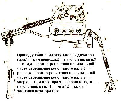
The control drive of the regulator and gas dispenser includes a system of levers and rods driven from the pedal through shaft 1 (Fig. 1)

A feature of the drive is a telescopic link 3. which ensures the movement of the fuel supply pedal by compressing the link spring (after limiting the stroke of the regulator lever with a stop) / thereby changing the position of the throttle valve of the gas dispenser.
In diesel mode, the link does not have a damping effect and acts as a rigid element, since its spring is stiffer than the governor lever spring.
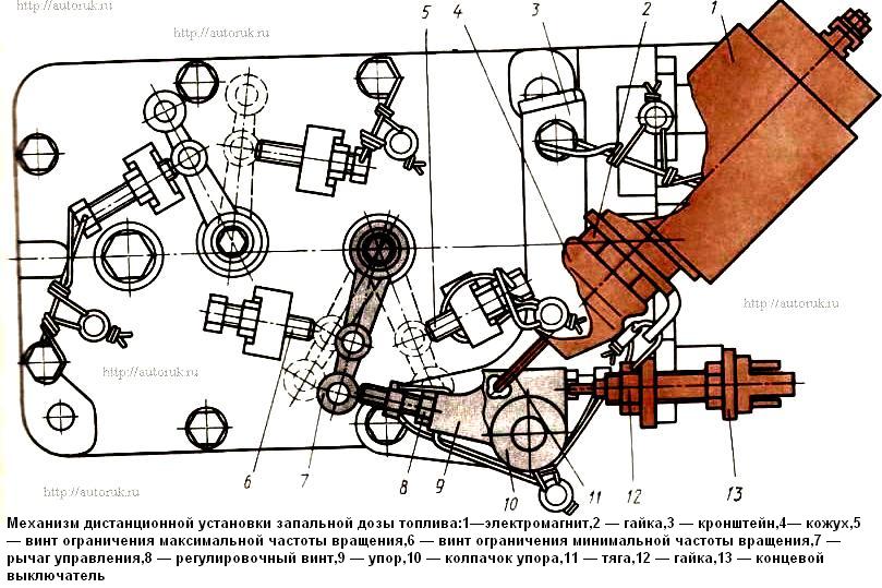
The mechanism for setting the ignition dose of fuel is located on the top cover of the speed controller.
With the help of this mechanism, when working in gas-diesel mode, the movement of the control lever 7 is limited (Fig. 1).
The mechanism consists of a bracket, which is fixedly fixed on the top cover of the speed controller, a movable stop 9 with an adjusting screw 8 mounted on an axis pressed into the bracket, a limit switch 13, an electromagnet 1 and a rod 11 connecting the core of the electromagnet 1 with the movable stop 9.
Electromagnet 1 and limit switch 13 are fixed on bracket 3.
When operating in diesel mode, electromagnet 1 is disabled, stop 9 is in the off position, limit switch 13 is open (gas is not supplied to the mixer).
The control lever 7 can be moved from the screw 6 of the minimum to the screw 5 of the maximum speed.
When operating in gas-diesel mode, electromagnet 1 is energized and it moves stop 9 to the working position.
At the same time, the limit switch 13 is activated, giving a signal that the stop 9 is set to the working position and it is possible to supply gas to the mixer.
Before switching to the gas-diesel mode, it is necessary to set the minimum idle speed, i.e. move the control lever 7 until it stops in the screw 6 of the minimum speed.
After the stop 9 has taken its working position, the control lever 7 can move from the screw 6 of the minimum speed to the adjusting screw 8 of the movable stop 9.
With further movement of the pedal, the control lever 7 remains stationary (the spring in the telescopic rod that connects the accelerator pedal to the control lever 7 and the gas damper is compressed).
In the event of a sudden failure of the electromagnetic control of the movable stop of the pump regulator lever, switch 13 turns off the gas supply circuit.


