The crank mechanism is the main working mechanism of the engine. It converts the reciprocating movement of the piston, which perceives the pressure force of expanding gases, into the rotational movement of the crankshaft
The elements of the crank mechanism can be conditionally divided into two groups: fixed and movable.
The fixed elements of the mechanism include cylinders, cylinder heads, crankcase with crankshaft bearings and connecting parts. All this forms the engine housing.
Moving elements of the mechanism: pistons with rings and piston pins, connecting rods with bearings, crankshaft with flywheel.

The cylinder block (fig. 1.) is a rigid monoblock V-shaped structure, cast iron as one piece with the upper part of the crankcase.
The high rigidity of the block is ensured by the division of the crankcase space into separate compartments by transverse partitions with power fins and a low location of the parting plane with the oil pan (significantly below the crankshaft axis).
In the upper part of the block at an angle of 90° there are two rows of cylinder sockets for insert sleeves with mating surfaces for cylinder heads.
The left row of cylinders is shifted forward by 29.5 mm relative to the right row, which is caused by the installation of two lower connecting rod heads on a common connecting rod journal of the crankshaft.
At the entire height of the cylinders, coolant passages are made, which ensures intensive heat removal from the cylinder liners, which improves the cooling of the pistons and piston rings.
The water jackets of the cylinder block and heads communicate through special holes in adjacent planes, sealed with rubber rings.
In the crankcase part of the block there is a system of channels for supplying oil from the central line to the crankshaft and camshaft bearings, parts of the gas distribution mechanism drive, oil filter, centrifugal filter, compressor and high pressure fuel pump.
The sockets in the block for the main bearing shells are calculated together with the covers, so the covers are not interchangeable and are installed in a strictly fixed position.
The crankcase part of the block is connected to the covers of the main bearings with transverse tie bolts.
Inside and outside the cylinder block there are parts of the crank and gas distribution mechanisms, assembly units (assemblies) and engine systems, as well as supports that attach the engine to the vehicle frame.
The bottom of the cylinder block is closed by a sump, which also serves as a reservoir for oil.
To avoid excessive pressurization or vacuum inside the crankcase, a breather is installed on the block.
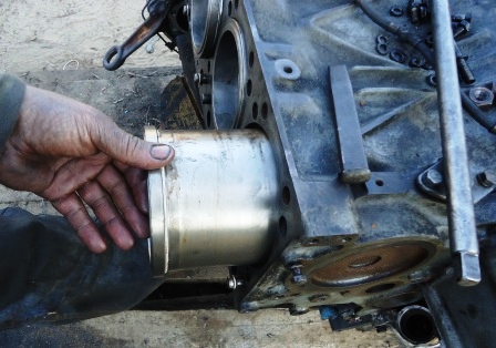
Cylinder liners are easily removable, made of special cast iron with pearlite structure by centrifugal casting and volumetrically hardened by high frequency currents to increase wear resistance.
The inner surface of the sleeve is flat-top honed to obtain a rare network of microcracks located at an angle to the axis of the sleeve.
This treatment helps to keep the oil in the depressions and better run-in of the sleeve.
The centering of the sleeve in the sockets of the block is carried out using the upper and lower processed belts.
In the upper part, the liner has a thrust shoulder with projections for installation on the thrust end of the cylinder block and reliable sealing of the gas joint with the cylinder head.
The water cavity between the block and the sleeve is sealed with rubber O-rings: in the upper part there is one ring under the shoulder in the groove of the sleeve, in the lower part there are two rings in the grooves of the block.
These rings protrude somewhat above the surface of the block belt and are crimped when installing the sleeve, creating a reliable seal.