The compressor is piston type, two-cylinder, single-stage compression, with a capacity of 220 l/min at a crankshaft speed of 2000 rpm and a back pressure of 700 kPa; installed on the front end of the flywheel housing.
The compressor drive is gear driven from distribution gears; head cooling from the cooling system, oil is supplied from the lubrication system.
The air enters the compressor cylinders through the air cleaner and the engine intake manifold through the vane inlet valves.
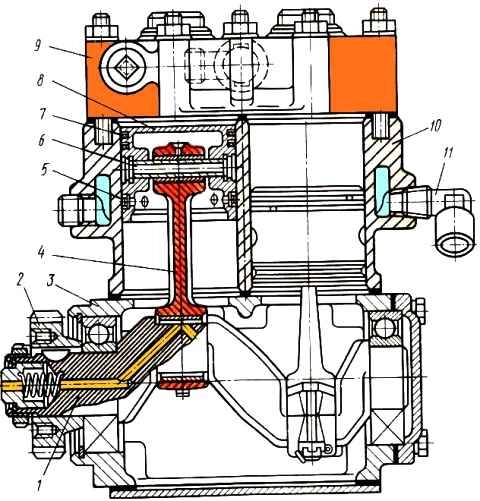
The air compressed by the pistons is forced into the receivers through plate discharge valves located in the cylinder head.
When the pressure reaches 700-750 kPa, the pressure regulator communicates with the pressure line to the atmosphere, stopping the air supply to the pneumatic system.
During seasonal maintenance, the compressor head must be removed to clean the pistons, valves and seats.
Compressor valves that do not provide tightness must be ground into the seats or replaced.
In the pressure regulator, it is necessary to wash or replace the filter element, which is located under the bottom cover.
You need to be careful when screwing in the cover, since the thread is conical and distortions when installing it are unacceptable.
They lead to thread failure, which is then impossible to restore.
Before installation, it is recommended to lubricate the thread with graphite lubricant to prevent it from “sticking.”
As the compressor operates, the cylinder-piston group wears out and the valve tightness is compromised.
In case of these malfunctions, the filling time of the pneumatic system (before the warning lights are extinguished) at a crankshaft speed of 2200 rpm exceeds the setting 8 minutes or the compressor does not develop the specified pressure at all (700-750 kPa).
In addition, wear of the cylinder-piston group leads to oil being sucked into the pneumatic system.
After filling the pneumatic system with air, the unloading valve in the pressure regulator opens and the oil that entered the pneumatic system along with the air is thrown out and settles on the regulator and frame. This is an external sign of a compressor malfunction.
It should be noted that oil consumption through the compressor may increase due to clogging of the air cleaner.
As clogging occurs, the vacuum at the inlet increases and the compressor, even with a working piston group, sucks in oil mist from the crankcase and then throws it out into the pneumatic drive at the outlet.
Leaking of the compressor cylinder head gasket, internal cracks in the head or block lead to the fact that liquid from the cooling system is sucked into the cylinders, and then, together with air, goes into the pneumatic drive.
The coolant level in the expansion tank drops, and the liquid in it bubbles.
This happens because the piston during the compression stroke pushes air into the compressor cooling jacket, and then the air and liquid are discharged into the expansion tank.
There is another dangerous consequence of the considered malfunctions
The liquid that has entered the compressor cylinders seeps into the compressor crankcase through the gaps between the cylinder, piston and rings and flows from it into the engine oil sump.
Therefore, when looking for where coolant gets into the oil, you must also keep in mind the compressor.
Brake malfunctions in most cases are caused by malfunctions of pneumatic drive devices.
Replacing the compressor
We replace the compressor in case of the following malfunctions:
- - wear of the compressor crankshaft bearings;
- - wear of parts of the crank and valve mechanisms, causing an increase in the oil content in the condensate drained from the receivers and a decrease in air pressure in the pneumatic system with a working pressure regulator and a sealed system;
- - mechanical damage to the cylinder block, crankcase and compressor head, impairing the operation of the compressor
Removing the compressor
Raise the cabin to the first position and lock it
Remove the vapor-air plug from the expansion tank and drain the liquid from the cooling system with the heater tap open
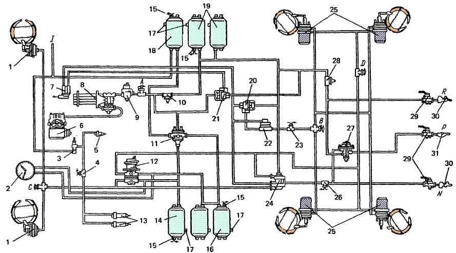
Bleeding air from condensation receiver 18 (Fig. 2)
Using a 22 mm wrench, unscrew the union nuts of the pipelines suitable for the expansion tank and disconnect the pipelines
Disconnect the fluid drain pipe from the expansion tank
Using a 13 mm wrench, unscrew the bolts of the clamps securing the expansion tank and remove the tank
Clean the outer surface of the compressor
Using a 22 mm wrench, unscrew the union nuts of the pipelines suitable for the compressor and disconnect the pipelines
Using a 10 mm wrench, unscrew the nuts securing the flange of the coolant supply tube to the compressor, remove the tube with the flange, gasket and o-ring
Unscrew the bolts securing the suction pipe to the compressor, using a 13 mm wrench, and disconnect the pipe
Using a 17 mm socket, unscrew the four bolts securing the compressor to the flange of the accessory drive flywheel housing
Disengage the compressor gear from the fuel pump gear by moving the compressor forward, and remove the compressor
Installing the compressor
Insert the compressor gear into the hole in the flywheel housing and into engagement with the fuel pump gear, having first checked the presence and serviceability of the sealing gasket
We screw in the four compressor mounting bolts using a 17 mm socket and a wrench
Attach the suction pipe to the compressor cylinder block (13 mm wrench)
Check the presence and serviceability of the flange gasket and o-rings on the tube, install and secure the flange securing the coolant supply tube to the compressor
Connect the pipelines to the compressor and secure them with union nuts
Install the engine cooling system expansion tank onto the bracket and secure it with clamps
Connect to the expansion tank and secure the fluid drainage pipe
We connect and secure with union nuts the pipelines suitable for the expansion tank
Fill the cooling system with liquid to the normal level and close the filler neck with a vapor-air plug
Start the engine, create pressure in the pneumatic drive of the brake systems. We make sure that the compressor is in good condition, that the air and liquid pipelines are tight, that there are no oil leaks from under the compressor mounting flange gasket
Lowering the cabin
Replacing the compressor discharge valve
The compressor discharge valve must be replaced if the following malfunctions occur:
- Wear, warping of valve and valve seat.
- Broken or weakened valve springs.
- Damage to the valve plug gasket.
An external sign of these malfunctions is a pressure drop in the pneumatic system of more than 49 kPa (0.5 krc/cm 2) in 1 minute with other compressor parts and sealed pipelines in good working order.
Removing the compressor discharge valve
You will need a screwdriver, a 10 mm square wrench, a 22 mm wrench, a 22 mm replacement head and a wrench
Raise the cabin to the first position and lock it
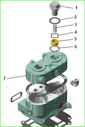
Compressor head: 1 – discharge valve plug; 2, 6 – gasket; 3 – spring; 4 – discharge valve; 5 – saddle pressure valve; 7 – compressor head
Unscrew the discharge valve plug 1 from the compressor head 7, remove the gasket 2 of the plug
Remove spring 3, discharge valve 4, unscrew and remove seat 5 with gasket 6
Perform transition 2 for the second valve
Installing the discharge valve
Install seat gasket 6, seat 5, discharge valve 4, spring 3, valve plug gasket 2 and screw plug 1 into the socket of the compressor head with a torque of 58.8 Nm (6 gcm)
Note. Before assembly, you need to lap the valve to the valve seat
We perform transition 4 for the second valve
Start the engine and check the operation of the compressor
Lowering the cabin
Replacing the compressor inlet valve
We replace the inlet valve in case of the following malfunctions:
- - wear, warping of the valve;
- - the presence of cavities on the valve;
- - broken or weakened valve springs
A sign of a malfunction is a pressure drop in the pneumatic system below 530 kPa (5.4 kgf/cm 2) with a working pressure regulator, other compressor parts and sealed pipelines
Removing the compressor inlet valve
Raise the cabin to the first position and lock it
Remove the vapor-air plug from the expansion tank and drain the liquid from the cooling system with the heater tap open
Bleeding air from condensation receiver 18 (Fig. 2)
Using a 22 mm wrench, unscrew the union nuts of the pipelines suitable for the expansion tank and disconnect the pipelines
Disconnect the fluid drain pipe from the expansion tank
Using a 13 mm wrench, unscrew the bolts of the clamps securing the expansion tank and remove the tank
Clean the outer surface of the compressor
Unscrew the union nut and disconnect the pipelines from the compressor head
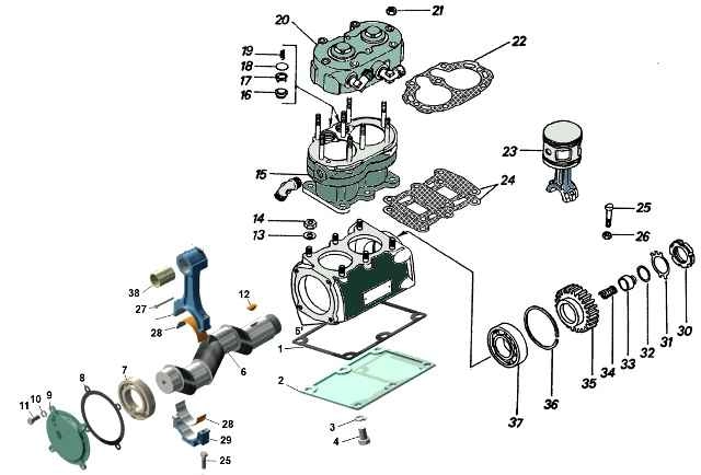
Air brake compressor: 1, 8, 22 – gaskets; 2 – lower crankcase cover; 3, 10, 13 – spring washers; 4, 11, 25 – bolts; 5 – crankcase; 6 – crankshaft; 7, 37 – bearings; 9 – cover; 12 – key; 14, 21, 26 – nuts; 15 – cylinder block; 16 – intake valve seat; 17 – intake valve guide; 18 – intake valve; 19, 34 – springs; 20 – compressor head assembly; 23 – piston with connecting rod; 24 – reflector plate; 27 – cotter pin; 28 – liner; 29 – connecting rod cover; 30 – thrust nut; 31 – lock washer; 32, 36 – thrust rings; 33 – seal; 35 – gear drive wheel
Unscrew the nuts 21 of the cylinder head studs, remove the head 20 and the head gasket 22
Note. When removing the head, prevent the springs 19 of the inlet valves 18 from falling out of their seats.
Remove the intake valves 18 from the sockets of the compressor cylinder block 15 using a screwdriver
Installing the compressor inlet valve
Insert intake valves 18 into the socket of the compressor cylinder block
Note. Before assembling, lap the valve to the valve seat 16
Place gasket 22 on the connector plane of the compressor cylinder block
Holding the intake valve springs in their sockets, install head 20 on the block. We secure the compressor cylinder head with nuts 21
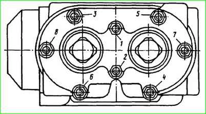
The cylinder head nuts must be tightened in the order shown in the figure, in pairs in two steps.
Final tightening torque 11.8-14.7 Nm (1.2-15 kgcm)
Install the parts in reverse order and check the operation of the compressor