Replacing the pneumatic booster with a hydraulic clutch drive
We replace the PGU if malfunctions occur:
- - jamming of the clutch drive (with a serviceable clutch master cylinder and clutch mechanism);
- - increased force on the clutch pedal - no boost (with a bled clutch hydraulic drive and a serviceable master cylinder and clutch mechanism);
- - mechanical damage to the pneumatic booster housing, disrupting its normal operation
Removing the pneumatic clutch booster
We prepare the car and release air from the consumer circuit
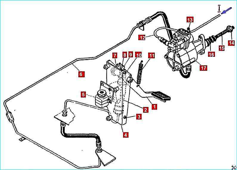
Clutch mechanism drive: 1 - pedal; 2 - main cylinder; 3, 10 - stops; lower and upper; 4 - bracket; 5 - expansion tank; 6 - hydraulic pipeline; 7 - lever; 8 - piston pusher; 9 - eccentric pin; 11 - release spring; 12 - pipeline; 13 - air release valve; 14 - spherical adjusting nut; 15 - pneumatic booster piston pusher; 16 - protective cover; 17 - PGU; I - compressed air
Remove the release spring 11 of the clutch release fork shaft lever
Disconnect the pneumatic line 12 of the clutch booster
Disconnect the hydraulic line 6 and drain the fluid from the clutch hydraulic drive
Unscrew the two bolts securing the pneumatic booster, release the pusher 15 from the lever, take it out and remove the pneumatic booster and the spring mounting plate
Installing the clutch booster
Insert the pusher 15 of the piston into the pneumatic booster and insert the other end into the hole in the clutch release fork shaft lever
Align the holes of the pneumatic booster with the holes in the clutch housing and secure with two bolts. Tightening torque of bolts 53.9-58.9 Nm (5.5-6.0 kgf/cm)
Connect hydraulic line 6
Connect pneumatic line
Install release spring 11 of clutch release fork shaft lever
Start the engine and fill the pneumatic system with air, the pressure in the system should be at least 637 kPa (6.5 kgf/cm 2)
Pour fluid into the master cylinder reservoir through the upper opening with the protective cover folded back and bleed the hydraulic drive system
Visually check the tightness of the pipeline connections and, if necessary, eliminate the leak
Adjust the free play of the clutch release fork lever
Repair of the pneumatic booster with hydraulic clutch drive
Disassembling the pneumatic booster
We install the pneumatic booster in a vice, holding the rear housing 55 with the jaws
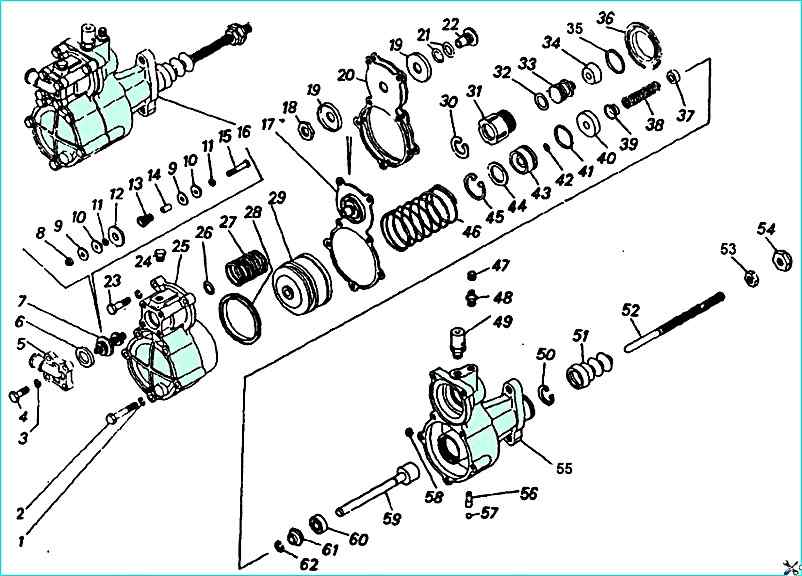
Pneumatic-hydraulic booster of the clutch control drive: 1; 3 - spring washers; 2, 4, 23 - bolts; 8 - cover; 6 - adjusting gasket; 7 - valve assembly; 8 - rod nut; 9, 11, 19, 44 - washers; 10 - cone; 12, 22 - seats; 13, 27, 46 - springs; 14 - tube; 15 rod; 16 - PGU assembly; 17 - diaphragm; 18, 53 - nuts; 20 diaphragm; 21 - seat fork; 24 front housing plug; 25 - front PGU housing; 26; 32; 35; 41; 42 Sealing rings; 28, 34 - cuffs; 29, 33, 59 - pistons; 30 - ring; 31 - housing; 36 - bushing; 37 - thrust bushing; 38 - spacer spring; 39, 61 - spacer bushing; 40; 60 - cuffs assembly; 43 - seal housing; 45; 62 - thrust rings; 47 - cap; 48 - valve; 49 - breather with valve assembly; 50 - retaining ring; 51 - cover; 52 - pusher; 54 - nut; 55 - rear housing; 56 - jet; 57 - ball; 58 - seat
Unscrew bolts 4 with washers 3 and remove cover 5 of air supply
Take out valve 7 of booster assembly from front housing of pneumatic booster
Unscrew bolts 2 and 23 with washers 1 and remove front housing 25 assembly with pneumatic piston 29
Remove spring 27 of membrane and spring 46 of pneumatic piston
Remove diaphragm 17 assembly of pneumatic booster
Unscrew follower piston 33 with housing 31 from rear housing 55 of booster
Take out thrust ring 45 and piston 59 of clutch release assembly from rear housing 55 of booster and housing 43 seals
Unscrew and remove the bypass valve 48 of the rear housing together with the cap 47
Unscrew the breather 49 of the outlet cover fastening, remove the cover and the seal of the outlet of the pneumatic booster
Remove the rear housing of the pneumatic booster from the vice
Take out the retaining ring 50 of the rear housing of the booster
Unscrew the nut 8 of the rod 15 of the valve
Remove the washer 9 from the rod 15 of the valve large, cone 10, small washer 11, valve seat 12, spring 13, tube 14, large washer 9, cone 10 and small washer 11 of the valve
Unlock at one point and unscrew the nut 18 of the reducer membrane
Remove washer 19 of membrane 20 and inserts 21 from seat 22
Remove sealing ring 35 from housing 31 of follower piston
Remove thrust ring 30 and follower piston 33 assembly from housing 31 of follower piston
Remove sealing ring 32 and cuff 34 from piston 33
Remove washer 44, housing 43 from piston 59 of clutch release piston seals assembled with sealing rings 41 and 42, piston seal cuff 40, spring 38, spacer sleeve 39, thrust ring 62, sleeve 61 and cuff 60
Remove pneumatic piston 29 assembled and sealing ring 26 from front housing 25
Remove cuff 28 from pneumatic piston 29
Wash pneumatic booster parts and blow them with compressed air and check technical condition
Checking pneumatic booster parts
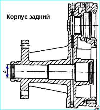
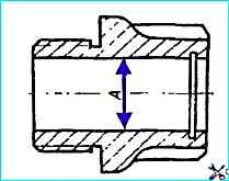
No traces of corrosion, nicks, or gouges on the working surface "A" of the housing, diameter "A" more than 28.06 mm, are allowed on the rear housing
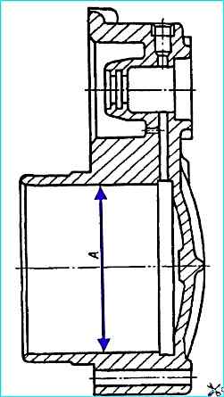
No allowed:
- - nicks, dents, nicks of the working surface "A" of the housing;
- - diameter "A" more than 90.2 mm.
The following are not allowed on the cuffs and sealing rings:
- - wear and swelling of the cuffs and sealing rings;
- - breaks and cracks in the working edges
Signs of aging (cracks, fractures, loss of elasticity) are not allowed on the outlet seal
Tears, cracks, loss of elasticity are not allowed on the membrane
The following are not allowed on the follower piston body:
- - nicks, scuffs, dents on the working surface "A";
Diameter "A" more than 28.06 mm
Assembly of the pneumatic booster
We install the cuff 28 on the pneumatic piston 29 (Fig. 2)
Apply grease 158 to the groove of piston 29
Install sealing ring 26 and pneumatic piston 29 in assembly in front housing 25
Install sealing ring 42 in housing 43
Note: from here on, before installing sealing rings and cuffs, lubricate them with NG-213 liquid
Put sealing rings 41 and 42 on housing 43
Install cuff 60, spacer sleeve 61, thrust ring 62, thrust sleeve 37, spacer spring 38, spacer sleeve 39, cuff 40, piston seal housing 43 in assembly with sealing rings 41 and 42 and washer 44 of the seal housing
Put on follower piston 33 assembled in housing 31
Install thrust ring 30 in housing 31 of follower piston
Put sealing ring 35 on housing 31
Put inserts 21, one washer 19, two membranes 20, then another washer 19 on seat 22 of membrane
Tighten nut 18 of membrane fastening
Lock nut 18 of membrane fastening
Lock nut 18 by pressing the edge of nut into groove at one point
Put small washer 11, cone 10, on stem 15 of booster valve, large washer 9, valve stem tube 14, small washer 11, cone 10, large washer 9, tighten nut 8
Install retaining ring 50 in rear housing 55 of the booster
Install rear housing 55 in a vice
Screw in breather 49
Install and tighten bypass valve 48 assembled with cap 47
Install clutch release piston in rear housing 55 of the booster
Install thrust ring 45 in assembled rear housing 55 of the booster
Screw follow-up piston 33 of the booster reducer with housing 31 assembled in rear housing 55
Install spring 46 of the pneumatic piston
Install the spring 27 and the membrane 17 of the amplifier gearbox assembly into the front housing 25, aligning the membrane holes with the holes of the front housing of the amplifier
Install the front housing 25 of the amplifier onto the rear housing 55 of the amplifier, screw in the bolts 2 and 23 of the fastening with spring washers 1
Install the gaskets 6 and the valve 7 of the amplifier assembly into the front housing 25 of the amplifier
Note: when installing the valve, it is necessary to adjust the weight with the gaskets 6 the original gap (2 +0.5 mm) between the reducer valve and the membrane seat. There should be at least one gasket.
Install the air supply cover 5 on the front housing 25 of the booster, aligning the holes, and screw in the mounting bolts 4 with spring washers 3
Remove the pneumatic booster assembly from the vice
Check the pneumatic booster for leaks and operability
The test is carried out on a stand made according to the diagram
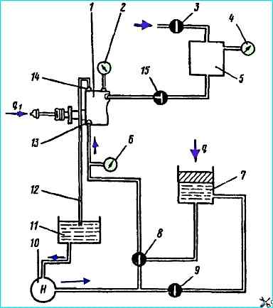
Test diagram of the pneumatic-hydraulic clutch booster: 1 - pneumatic-hydraulic booster; 2, 4, 6 - pressure gauges; 3, 8, 9, 15 - taps; 5 - compressed air reservoir; 7 - control cylinder with brake fluid; 10 - pump; 11 - reservoir; 12 - pipeline; 13, 14 - bypass valve
Before checking, the hydraulic system must be filled with brake fluid.
Fill the brake fluid and bleed air using pump 10 reservoir 11 and bypass valve 14 installed on the pneumatic booster
When pump 10 is running, it is necessary to unscrew the bypass valve by 0.5 turn for 3-4 seconds.
This will release air from the hydraulic system through pipeline 12 into reservoir 11. After all the air has come out, close the bypass valve.
At the same time, using pump 10 and tap 9, the control cylinder is filled with working fluid
We check the hydraulic system of the booster for leaks using the control cylinder 7. In this case, tap 15 of the pneumatic system must be closed (there should be no air in the pneumatic system)
During the hydraulic system leak test, stop "q1" must be firmly fixed. In this case, the load "q" must provide a pressure in the hydraulic system of the booster of 5.8 MPa (60 kgf/cm 2) according to the pressure gauge 6
During the test, the presence of brake fluid leaks through the seals in the booster elements is not allowed
The piston of the control cylinder 7 under the action of the load "q" must be motionless for one minute
The tightness of the pneumatic system is checked using the compressed air tank 5.
During the test, the tank 5 must be under an air pressure of 687 kPa (7 kgf/cm 2) with the valve 3 closed.
With valve 15 open, air leakage through the booster reducer is not allowed.
In this case, the air pressure in the tank 5, monitored by the pressure gauge 4, must not decrease within one minute acceptance check
The performance check is performed with all elements of the pneumatic booster working together.
A dynamometer must be installed to check the tests on the stop (q1).
The load q must have three values A 1, A 2, A 3, providing pressure in the hydraulic system of the booster (P) 784, 1156, 1569 kPa (8, 12 and 16 kgf/cm 2).
The air pressure supplied to the pneumatic system during testing must not fall below 589 kPa (6 kgf/cm 2).
When loading the control cylinder 7 with load (q) according to the three above values, the force on the pusher rod must correspond to the graph
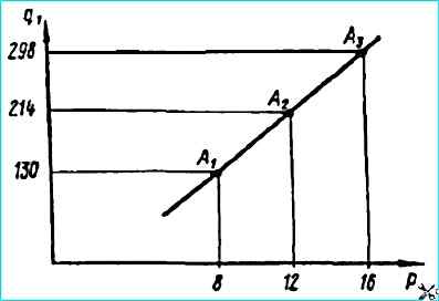
When held at each point indicated on the chart for 15 seconds, the readings of pressure gauges 2, 6 of the dynamometer should not change