According to the ignition method, gas-diesel can be classified as a forced-ignition engine
Its working process differs from the working process of spark-ignition engines in that the electric spark as a source of ignition of the working mixture is replaced by a dose of diesel fuel
At the end of the compression stroke, a small (pilot) dose of diesel fuel is injected into the heated air-gas charge.
The ignition dose of fuel is supplied to the cylinder in such a way that it ignites earlier than the gas and ignites the entire mass of the gas-air mixture.
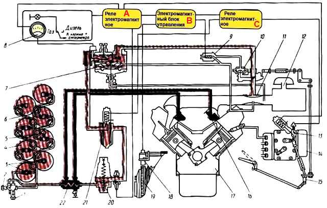
Diagram of a gas cylinder installation: 1 - filling valve; 2 - flow valve; 3 - shut-off valve; 4 - balloon; 5 - high pressure gauge; 6 - high pressure pipeline; 7 - low pressure reducer; 8 - pressure gauge; 9 - three-way solenoid valve; 10 - dispenser; 11 - mixer; 12 - air cleaner; 13 - mechanism for limiting the pilot dose of fuel; 14 - high pressure pump; 15 - control drive for the regulator and gas dispenser; 16 – tap; 17 - engine; 18 - speed converter; 19 - ring gear; 20 - high pressure reducer; 21 - solenoid valve with filter; 22 - gas heater; A - electromagnetic relay; B - control unit; C - electromagnetic relay
When converting a diesel engine to operate in gas-diesel mode, a gas-air mixer with a system for regulating the gas supply when the load changes and an upgraded crankshaft speed controller with a fuel supply limiter when the engine is operating in gas-diesel mode are added to the design of the power system.
This conversion method allows for a quick transition from diesel to gas-diesel mode and back.
Information about gas diesel fuel
Compressed natural gas is used as the main fuel in gas-diesel engines.
The characteristics of compressed natural gases used as motor fuel must comply with the requirements of TU 51-166-83, which establishes two grades of gas: “A” and “B”.
These gases retain a gaseous state at normal ambient temperatures and high (up to 20 MPa) pressure.
The main component of natural gas is methane, which is a valuable fuel with good anti-knock characteristics and a fairly high specific heat of combustion.
Natural gases also contain harmful impurities, the percentage of which is limited by technical conditions.
These include toxic gases (hydrogen sulfide and carbon monoxide), non-flammable gases (nitrogen, carbon dioxide) and moisture.
Carbon monoxide (CO) and hydrogen sulfide (H2S) have a strong toxic effect on the human body; in addition, hydrogen sulfide during combustion forms sulfur compounds that destroy engine parts and gas equipment.
The CO content in the gas should not exceed 1%, and the mass of hydrogen sulfide in 100 m 3 should not exceed 2 g.
The presence of moisture leads to the formation of plugs in pipelines at subzero temperatures and gas reduction.
With sulfur compounds, moisture forms acids that cause corrosion of the walls of cylinders and pipelines.
Odorization of compressed natural gas allows you to determine the presence of gas in the workplace and in the work area by smell.
When odorizing, 0.016 g of mercaptan sulfur is added per 1 m of 3 gas.
In terms of toxicological hazards, the maximum permissible gas concentration at workplaces and in work areas should not exceed 300 mg/m 3. It is determined using gas analyzers.
Due to the fact that methane is much lighter than air, ventilation suction and gas alarm sensors should be installed in the upper part of the premises for the maintenance and repair of gas-diesel vehicles.
In addition to the listed impurities, natural gas contains other flammable gases: propane, ethane, butanes and pentanes, the percentage of which is insignificant, therefore the properties of compressed natural gases are determined by their main component - methane (CHc).
Flammability limits characterize the concentration of gases in a mixture with air at which engine operation is possible.
Natural gas at a temperature of +20 °C and normal pressure has a flammability limit: lower - 4%, upper - 15% of the gas content in the volume of air. At this concentration, the mixture of gas and air is explosive.
The gas compressibility coefficient takes into account the disproportionality of the change in its volume with increasing pressure.
For methane, the compressibility coefficient at 0°C with a pressure change from 0.1 to 20 ranges from 1 to 0.82.
Taking into account the compressibility coefficient at gas filling stations, tables of vehicle cylinder capacity.
Gas cylinder installation
In a gas-cylinder installation, store natural gas in a compressed state of up to 20 MPa in cylinders.
The reserve of natural gas in one cylinder at a pressure of 20 MPa is about 10 m 3.
To ensure a range of 250...300 km, six, eight or ten cylinders can be used, depending on the car model.
The figure shows a diagram of the gas cylinder installation of the KamAZ-54118 truck tractor with eight cylinders 4.
The package of cylinders consists of two sections of four cylinders each. This scheme allows the engine to operate on the gas reserves of one section when the seal in another is broken.
Cylinder sections, each of which has a shut-off valve 3, are connected to a cross with 1 filling valve and 2 supply valve.
During engine operation in gas-diesel mode, valves 2 and 3 are open.
Compressed gas under high pressure passes through the heater 22, in which the coolant is the liquid of the engine cooling system, and enters the single-stage high-pressure gas reducer 20, where the gas pressure is reduced to 0.9-1.1 MPa.
On the way to the reducer, the gas is heated to avoid ice plugs in the pipeline, which can form due to strong cooling of the gas when the pressure in the reducer sharply decreases.
Then the gas is supplied to filter 21 with a felt element and an electromagnetic valve, and from it to a two-stage gas reducer 7, where its pressure is reduced almost to atmospheric pressure.
The operation of the gearbox is controlled by vacuum transmitted to it through a tube from the mixer diffuser 11.
From the reducer, gas enters the mixer through dispenser 10, where a gas-air mixture is formed, and then, together with air, is sucked into the engine cylinders.
The gas pressure in the cylinders, and therefore the fuel supply in them, is controlled using a high-pressure pressure gauge 5. Using low pressure pressure gauge 8, the operation of the first stage of the gearbox is checked.
An electromagnetic mechanism 13 is installed on the cover of the crankshaft speed regulator, which limits the travel of the regulator control lever from the position of the minimum idle speed to the position corresponding to the supply of the pilot dose of fuel.
The engine is switched to gas-diesel mode after starting and warming up the diesel engine to a coolant temperature of at least 50°C by switching the key on the cockpit instrument panel to the “Gas” position.
Electric engine control system. For this purpose, the vehicle is equipped with additional gas-diesel electrical equipment.
It also includes a gas supply limitation system: when the crankshaft reaches maximum rotation speed, when the mechanical speed regulator turns off the supply of the pilot dose of liquid fuel, and an electrical lock that prevents the simultaneous supply of gas and the full supply of liquid diesel fuel (double thrust).
Cylinders for compressed gas. Cylinders are designed for storing and transporting gas fuel and are the most critical components of a car’s gas equipment. The safety of vehicle operation depends on their reliability and tightness.
The cylinders are designed for a working pressure of 20 MPa. They are made from seamless seamless pipes by rolling the bottoms and necks.
To increase strength and ensure shatterproofness in case of destruction, they are subjected to heat treatment, hardening and tempering.
Currently, two types of cylinders made of carbon or alloy steel are used.
Regular carbon steel cylinder with a capacity of 50 liters. has a mass of 93 kg.
The alloy steel cylinder has the same capacity, but its weight is no more than 65 kg.
Finished cylinders are tested for strength and tightness of connections with fittings.
Usable cylinders are painted red and the following passport data are stamped on the front bottom: manufacturer's trademark, cylinder number, weight, date of manufacture and year of the next test, operating pressure and test pressure, capacity, stamp of the quality control inspector of the plant, manufacturer and standard number.
Let's consider an example of designating the dates of manufacture and the next test 10-89-94 - the cylinder was manufactured and tested in October 1989, repeated hydraulic tests should take place in 1994
The area on the cylinder with passport data is coated with colorless varnish and surrounded by a colorful frame.
The neck of the cylinder has a hole with a conical thread into which an adapter for connecting tubes is screwed
A necessary condition for the correct mouth New adapter in the cylinder - the presence of 3-4 spare threads on the adapter.
The cylinders are connected to each other by high-pressure gas pipelines. They are made from seamless steel tubes with an outer diameter of 10 mm and a wall thickness of 2 mm.
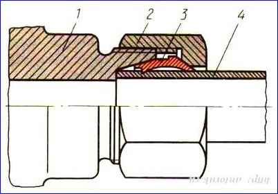
Gas pipelines are connected without gaskets. The tightness of the connections is achieved by cutting nipple 3 into tube 4 and tightly pressing the end of the tube to the connecting fitting 1 using union nut 2.
The nipple connection allows for repeated disassembly. When installing a new nipple, you must ensure that it is located at a distance of about 1.5-2 mm from the end of the tube.
When the union nut 2 is tightened, nipple 3 is deformed and takes the shape of an internal conical hole in the fitting, ensuring the tightness of the connection.
At the same time, the nipple cuts a sharp edge into the walls of the tube, preventing it from being pulled out of the connection under the influence of high pressure.
The tightening force of the union nut during the preliminary insertion of the ring should be 40-56 N.
The nipple must be tightly seated on the tube. If, after tightening the nut, the nipple does not ensure a tight connection, then it should be replaced together with the gas pipeline.
Preliminary soldering of the nipple with solder and flaring of the ends of the tubes are not allowed.
If the nipple connection does not provide complete tightness after tightening nut 2, it should be replaced.
To do this, nipple 3 is cut off together with a piece of tube, the end of the tube at a length of 13-15 mm is cleaned of paint and anti-corrosion coating and a new nipple is installed on it.
To compensate for the twisting forces that are transmitted through the cylinders to the gas pipeline during possible deformations of the car frame, the high-pressure tubes are bent so that they form compensation rings.
These rings also compensate for the reduction in tube length when replacing the nipple.
The cylinders on the car are secured with brackets and clamps.
Displacement of cylinders due to loosening of their fastenings can cause rupture of high-pressure gas pipelines in the nipple connection.
Pipe breaks, as a rule, are accompanied by serious consequences, including fire. Therefore, the fastening of the cylinders must completely exclude the possibility of their movement.
Particular attention should be paid to strengthening the cylinders using clamps. Tightening the clamps until their ends touch is not allowed.
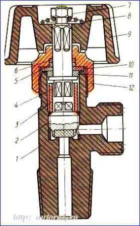
Valves
The gas cylinder installation has four valves: two cylinder valves, a filling valve and a supply valve (main).
Cylinder valves are used to connect sections of cylinders to a common line.
The filling valve is designed for filling compressed gas cylinders.
The filling valve fitting has a special left-hand thread and is closed with a plug that protects it from dirt and moisture.
On other valves, fittings have right-hand threads.
To connect gas pipelines, an adapter is installed on this fitting, sealed with a gasket. Otherwise, all valves are designed the same; their design is shown in the figure.
")

")
")
")
")
")
")
")