KAMAZ power steering control valve
The power steering control valve (Fig. 2.) is attached to the bevel gear housing
The valve body 8 has holes made with great precision - one central and six (three through and three blind) holes of smaller diameter located around it.
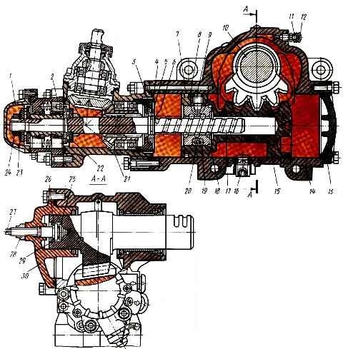
Spool 6 of the control valve, located in the central hole, is secured to screw 17 (see Fig. 1.) through bearings 22 with a nut 24, the collar of which is pressed into the groove of screw 17 for fixation.
Under the nut) there is a conical spring washer 23, ensuring a constant tightening force of the thrust bearings.
The concave side of the washer is installed towards the bearing.
The large thrust bearing rings face the spool.
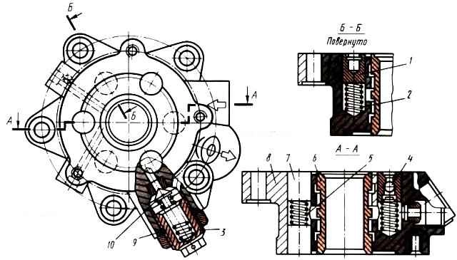
Valve body 8 (Fig. 2) is equal in length to the length of the spool, but has recesses at the ends.
The grooves allow the spool with screw and thrust bearings to move axially 1.1 mm in each direction from the middle position.
A ball check valve 4 is built into one of the plungers located in the blind holes, which connects the high and low pressure lines in the event of a failure of the steering hydraulic system, maintaining the ability to drive the vehicle.
In this case, the steering operates like a conventional mechanical system without power assistance.
A safety valve 10 is also installed in the control valve housing, connecting the discharge and drain lines when the pressure in the system exceeds 80 mPa, and thus protects the pump from overheating and the mechanism parts from overload.
The safety valve is located in a separate boss, which allows you to check, adjust or replace it if necessary without disassembling the mechanism.
High and low pressure pipelines are connected from the pump to the control valve body.
The first one sends the oil to the mechanism, and the second one returns it to the hydraulic system reservoir.
To cool the oil, the power steering system includes a radiator, which is an aluminum finned tube located in front of the radiator of the engine cooling system.