Model 5320 has a three-seater cabin without a berth, model 5410 has a berth
Models 54112, 53212 can be equipped with a cabin with or without a berth at the customer's request.
Dump trucks of models 55111 and 55102 have a cabin without a berth, at the customer's request a middle seat for a passenger can be installed, fixed, with a folding back.
The cabin has a spring suspension, providing reliable isolation from the impact of the road.
To service the engine, the cabin is tilted forward. In the operating position, the cabin is held by two lever-type locking devices.
The cabin doors are equipped with lowering glass and pivoting vents. Windscreen glass is safe, of the “triplex” type.
The windscreen cleaning and washing device is electric, consists of an electric motor with a gearbox, rods and brushes, a tank with an electric pump located in the cabin under the instrument panel, tubes, jets and control keys.
Natural ventilation through windows and door vents, a ventilation hatch in the roof, as well as a heating system operating from the engine cooling systems with forced air supply to the feet of the driver, passengers, windscreens and door windows.
This allows you to set the optimal temperature in the cabin at any time of the year, and protects the glass from freezing.
The cabin is equipped with reliable multi-layer heat and sound insulation and soft upholstery.
The driver's seat and the outer passenger seat are adjustable, which provides optimal conditions for the driver to work and rest of the shift worker.
The cabin is equipped with seat belts for all three seats of the cabin.
Special aerodynamic devices: side fairings, roof fairings, the installation of which is provided for on the cabins, reduce the aerodynamic resistance of the vehicle, increase fuel efficiency, reduce pollution of the vehicle when driving on wet roads.
The vehicle cabin consists of the following main parts: the body, doors, glazing, seats, heat and sound insulation and interior parts, equipment, as well as plumage parts (wings, footrests, trim panel, etc.) and cabin mounting parts.
In the modernized vehicles, the following changes have been made to the cabin design:
- - the height of the cabin roof has been increased;
- - rotary door locks have been installed;
- - three sun visors have been installed (instead of two);
- - a cable window lift is installed;
- - a set of spherical mirrors is installed;
- - the hook and handles of the cabin locks are changed;
- - the tool box is installed under the passenger seat;
- - an above-window shelf is installed;
- - the location of the fuel pedal and brake pedal is changed;
- - the connection location of the cabin heating system for vehicle configurations with the KAMAZ-740.11 engine is changed;
- - an original front panel is installed (the location of the headlights is changed);
- - original fairings are installed;
- - the engine compartment panel on the cabin without a berth is canceled;
At the request of the buyer, an aerodynamic visor can be installed and a supergraphics.
Cabin body
The cabin body is the power part of the cabin and the basis for fastening all units and equipment.
The cabin body is all-metal, assembled by spot welding from stamped panels, pre-assembled into assembly units: base, front, two side panels, rear and roof.
Moreover, cabins without a berth and with a berth are maximally unified with each other.
Only the roof of the cabin with a berth differs, and side extensions and the middle panel of the rear (the berth itself) are added.
All cabin panels are made of thin sheet steel with a thickness of 0.9 to 1.2 mm. The rigidity of the panels is ensured by ribs stamped in the panels and panel frames.
At the junction of the panels, complex closed sections of the cabin frame tank are formed, which, together with the frames of the panels themselves and the panels, create the power scheme of the cabin and ensure high rigidity and strength of the cabin.
Cabin fastening
The cabin is attached to the frame at four points using two front hinged supports and two rear sprung supports with a locking mechanism.
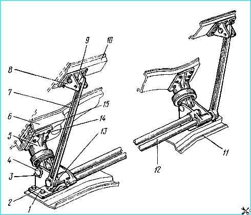
Front fastening and mechanism cabin balancing: 1 - lower bracket; 2-tie bolt: 3 - lock washer; 4 - pin (axle); 5 - upper bracket; 6 - front floor beam; 7 - torsion arm; 8 - torsion arm support; 9 - support bushing; 10 - floor reinforcement; 11 - first cross member of the frame; 12 - torsion bar; 13 - torsion bar bushing; 14 - plate; 15 - floor crossbar insert
The front hinged supports (Fig. 1) consist of lower brackets 1, bolted to the first crossbar of the frame, and upper brackets 5, which are attached to the floor crossbar.
The hinged connection between them allows the cabin to be tilted forward.
Two rubber sealing rings are inserted into the hinge hole of the upper bracket, which prevent moisture and dirt from getting between the rubbing surfaces and retain grease.
Rubber cushions are built into the upper brackets to soften vibrations transmitted from the frame to the cabin through the front supports.
Torsion bars 12 of the cabin balancing mechanism are fixed in the lower brackets of the front cabin mount.
The rear cab mount (Fig. 2) is combined with the soft cab suspension and consists of two longitudinal leaf springs 1, which are attached to brackets 13, rigidly fixed to the frame side member 14, and two hydraulic telescopic shock absorbers 11, which are fixed to the bracket with the lower eye, and in the spring housing 9 with the upper eye.
The bracket 6 of the locking mechanism is attached to the spring housing, to which the locking device attracts the cab.
The downward movement of the cab is limited by the rubber buffer 10, which rests against the frame when the spring travels more than 25 mm.
The shock absorber of the cab suspension mechanism is similar in design to the shock absorbers of the front suspension vehicle.
At a piston speed of 0.25 m/s, the control data for the shock absorber resistance forces during the compression stroke are 94.2-259 N (9.6-26.4 kgf), during the rebound stroke - 895-1271 N (91.2-129.6 kgf).
The cabin tilting mechanism (see Fig. 2) serves to facilitate tilting the cabin forward when servicing the engine and should ensure almost complete balancing of the cabin in any inclined position.
The cabin tilting mechanism consists of two interchangeable torsion bars 12, which are secured with their square ends in the lower brackets 1 of the front supports, and are freely installed with their splined ends in the rubber bushings 13 of the opposite brackets.
Interchangeable levers 7 are secured to the splined ends with tie bolts 2 torsion bars, whose upper ends rest against the bushings 9 of the 8 torsion bar supports.
When the cabin is in the transport position, the torsion bars are twisted at an angle of 53º.
The cabin tilts at 42º and, if necessary (to remove the engine), can tilt at 60º. To do this, release the extension of the cabin lift limiter.
Some vehicle models have a cabin lifting and lowering mechanism (Fig. 3) with a hydraulic drive and manual control.
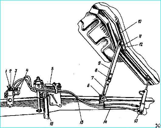
Cab lifting and lowering mechanism: 1 - control handle; 2 - drive handle; 3 - hydraulic pump; 4 - tank; 5 - cabin suspension; 6 - lower bracket; 7 - lower limiter post; 8 - safety pin; 9 - upper limiter post; 10 - cabin longitudinal beam; 11 - extension pin; 12 - upper bracket; 13 - hydraulic cylinder; 14 - hydraulic drive; 15 - side member; 16 - front suspension shock absorber
The mechanism consists of a hand pump with a tank, filters and rotary valves equipped with handles, a cylinder for raising and lowering the cabin, oil supply pipes connecting the pump and the cylinder.
A tire mounting blade or a ratchet for a wheel wrench is used as a pump handle.
The pump for raising and lowering the cabin (Fig. 4) is a plunger type, with a tank, mounted on a bracket located on the rear of the right front wing of the car.
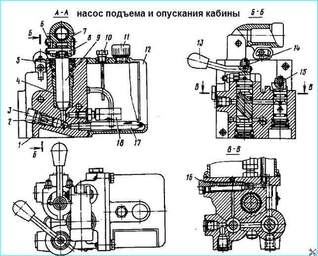
Cabin lifting and lowering pump: 1 - pump body; 2 - spring; 3 - plug; 4 - delivery plunger bushing; 5 - wiper; 6 - pin; 7 - pump handle; 8 - pressure pin; 9 - delivery plunger; 10 - plug with dipstick; 11, 18 - safety valves; 12 - tank; 13 - spool valve handle; 14 - reversible spool valve; 15 - spool valve; 16 - pump jet with filter; 17 - suction filter
To limit the pressure in the system, a ball safety valve is provided, which bypasses oil into the tank at a pressure of 15 MPa (150 kgf/cm 2).
The pump body has threaded holes to which the nipples of the oil supply pipes connected to the cylinder are connected through elbows screwed into these holes.
Oil is supplied to the corresponding nipples by turning the handle 13 of the control spool in one direction or another until it stops.
The handle of the spool 14 has adjusting stops that are locked with nuts.
The cabin is raised and lowered by turning the handle of the spool in the direction of the arrows: arrow up - raise the cabin, down - lower.
For safety when When the cabin is lowered, the oil from the hydraulic system returns to the tank through the nozzle 16 with a filter that prevents the system from becoming clogged.
Tank 12 is attached with screws to the pump body; The tank has a filler cap 10 with a dipstick, a safety valve 11 that limits the pressure in the tank cavity to 20-30 kPa (0.2-0.3 kgf/cm 2).
The cabin lifting and lowering cylinder (Fig. 5) is equipped with safety valves (Fig. 6).
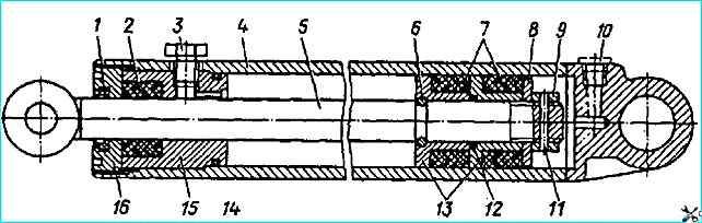
Cab lifting and lowering cylinder: 1 - rod wiper; 2, 7 - cuffs; 3 - plug; 4 - cylinder cup; 5 - rod; 6 - rod half rings; 8 - washer; 9 - nut; 10 - transport plug; 11 - pin; 12, 14 - sealing rings; 13 - cuff bushings; 15 - cylinder cover; 16 - cover nut
On the cabin lifting and lowering cylinder, the valves are installed on the outlet openings closed with plugs.
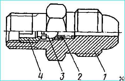
Safety valve: 1 - body; 2 - spring; 3 - ball; 4 - plug
Safety valves, which are check throttle valves, close when a hose ruptures or other damage to the system causes rapid lowering of the cabin, and the lowering of the cabin stops.
The valves can also close when the oil supply is too sharp; in this case, to open the valve, the spool handles must be turned to the position opposite to the operation being performed (if the cabin was lowered, then set the handles to the lifting position, and then to the previous position and continue lowering).
Lifting the cabin. Before lifting the cabin, it is necessary to brake the vehicle with the parking brake system and set the gearshift lever to the neutral position.
Then it is necessary to turn the handles of both cabin locks to the extreme upper position and disengage the safety hook of the right lock.
To lift the cabin to the first position (at an angle of 41º), set the handles on the pump to the "Cabin lift" position and, pumping the pump handle with a mounting blade, lift the cabin.
To prevent accidental lowering of the cabin, it is necessary to secure the limiter posts with pin 17.
To lower the cabin, remove the locking pin, set the handles on the pump to the "Cabin lowering" position and, pumping the pump handle with a mounting blade, lower the cabin.
To raise the cabin to the second position (at an angle of 61º), remove front buffer, raise the front trim panel and lower the cabin to the first position; unpin and remove pin 15 of the extension.
Then use the hydraulic lift to raise the cabin to the second position.
The cabin lift limiter (Fig. 7) is located on the right side of the cabin.
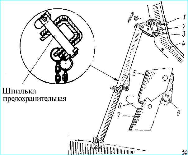
Cab lift limiter: 1 - extension pin; 2 - upper bracket; 3 - extension; 4 - longitudinal beam of the cabin floor; 5 - upper post; 6 - hook-latch; 7 - lower rack; 8 – buffer
The lower post 7 of the limiter rotates in a bracket fixed to the right side member of the frame.
The upper post 5 is secured via an extension 3 in a bracket 2 fixed to the longitudinal beam 4 of the cabin floor.
When the cabin is raised, both posts create a stop that prevents the cabin from lowering itself.
To prevent accidental folding of the limiter, there is a safety hook-latch 6 between the lower and upper posts.
When lowering the cabin, it is necessary to pull this latch and move the limiter towards yourself.
For cabins with hydraulic lifting, a safety pin is used instead of a hook-latch (Fig. 7).
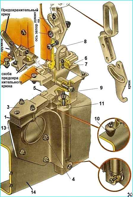
The cabin locking mechanism (Fig. 8) fixes the cabin on rear supports in trunloaded position and consists of two mechanical locks with a safety hook on the right locking device.
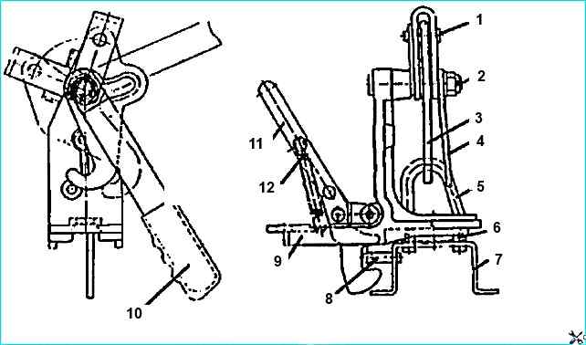
The lock body is attached to the rear beam and the longitudinal beam of the cabin floor. The lock handle rotates on the lock axis. The hook rotates on the axle pin.
When the cabin is secured, the housing with its groove enters the bracket welded to the bracket fixed to the spring collar, and the hook engages with the bracket.
The hook design ensures that when the lock is closed, the lock housing is pulled up to the rubber pad on the bracket bracket.
The safety hook is automatically latched onto the bracket by means of a spring.
To open the lock before tipping the cabin, turn the handles of both locks from the lower position towards you, to the upper position, while the hook disengages from the bracket, then disengage the safety hook.