Remove the cabin for replacement and repair
Removing the cabin
Lift the front trim panel of the cabin
Drain the coolant through the drain cock of the lower radiator pipe with the heater cock open
Disconnect the air supply hoses to the pressure gauge, the parking brake valve from the fittings secured to the left and right of the heater radiator on the flexible hose mounting brackets
Disconnect the hydraulic line 6 and drain the fluid from the clutch hydraulic drive
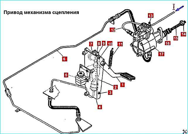
Disconnect the clutch hydraulic hose from the master cylinder pipe by unscrewing the hose tip from the fitting passing through the hole in the cabin floor
Loosen the clamps of the inlet and outlet hoses of the cabin heater and disconnect the hoses from the heater radiator

Unpin the pin 13 of the intermediate fuel supply control rod, remove the pin and disconnect rod 12 from the two-arm lever 14 of the accelerator
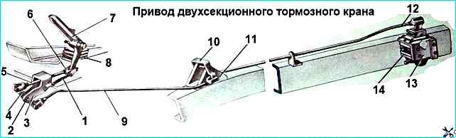
Unpin pin 2 of the brake valve control rod, remove the pin and disconnect rod 9 of the drive from intermediate lever 4
Disconnect the cardan shaft fork from the end of the steering gear angular gearbox gear wheel
Unscrew the bolt securing the ground wire to the cabin
Disconnect the electrical wires from the electromagnetic valve of the fuel electric heater and the spark plug of the starting heater
Disconnect the radiator shutter drive cable from the bracket, release it from the fastening to the low pressure pipeline of the steering gear. We take the cable out of the hole in the cross member of the car frame
We disconnect the plug connectors and disconnect the wire bundle from the cabin panel
We remove the front bumper, disconnect the plug connector of the front lights
We tilt the cabin to the first position

Unpin the pins 1 of the upper bracket 2 and extension 3, remove the pins and disconnect the cabin lift limiter
Lower the cabin onto the rear supports
Lower the door windows and close the cabin doors
Insert special grips into the window openings of the doors, moor the cabin (this operation is performed by two people)
Remove the lock washers, knock out the pins of the front supports or unscrew the 12 bolts securing the brackets to the cabin
Lift the cabin, move it forward and install it on the stand
Installing the cabin
Insert special grips into the window openings of the doors, moor and lift the cabin. Install the cabin on the frame
Insert the pins of the front cabin supports into the brackets and secure the pins with lock washers or screw in 12 bolts to secure the cabin to the brackets (the operation is performed by two people)
Raise the cabin, insert pins 1 (Fig. 4) of the upper bracket 2 and extension 3 of the lifting limiter to abins, we cotter pin the fingers
We lower the cabin onto the rear supports
We install and secure the front buffer. Connect the plug connector of the front lights
Connect the plug connectors and secure the wire bundle to the cabin panel
Connect the radiator shutter drive cable
Connect the electric drive to the electromagnetic valve, electric fuel heater and spark plug of the pre-heater
Connect the ground wire to the cabin
Connect the cardan shaft fork to the end of the angular gearbox gear
Connect the intermediate lever 4 (Fig. 3) to the drive rod 9, inserting pin 2. Cotter the pin
Connect the intermediate rod 12 of the fuel supply control (Fig. 2), inserting pin 13, cotter the pin it
Connect and secure the inlet and outlet hose of the cabin heater to the heater radiator
Connect the clutch hydraulic hose to the master cylinder pipe by screwing the hose tip into the connecting nipple
Connect the hydraulic pipeline 6 (Fig. 1)
Connect the air supply pneumatic hoses to the pressure gauge, emergency brake release valve, parking system valve, to the pipe nipples secured to the hose mounting brackets (on the front panel of the cabin)