We dismantle the winch for replacement or repair
We replace the winch in the event of the following faults:
- - oil leak through the cuffs as a result of their damage;
- - breakage of the cracker and destruction of the turns of the lead screw of the cable guide;
- - deflection of the guide shafts of the cable guide and jamming of the guide rollers;
- - wear of the hole under the end of the cracker in the body of the cable guide;
- - wear or breakage of the teeth of the globoid pair of the winch gearbox;
- - cracks or holes in the winch housing
To complete the task, you need tools: wrenches 12x13, 14x17, 17x19, 22x24, open-end wrench 19x22, screwdriver, hammer, crowbar, mounting blade, lifting and transport device for removing gearboxes, slinging device
To do this, remove the winch cable:
Unscrew the clamp nuts and remove the two platform flooring boards located above the winch
Loosen the cable fastening manually by turning the winch gearbox engagement lever
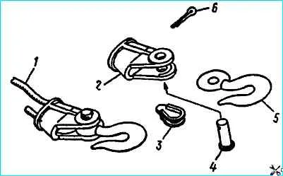
Uncotter and remove pin 4 (Fig. 1) and hook 5, knock out wedge 3, remove thimble 2. Pull the cable back
Start the engine, fill the pneumatic drive of the brake systems with air. Engage the parking brake system
Set the transfer case control switch to neutral
Set the power take-off control switch to the "on" position
Engage reverse gear in the gearbox
Unwind the cable
Notes: take up the slack in the cable manually. If necessary, you can unwind the cable manually. To do this, turn off the winch drum shaft by turning the lever.
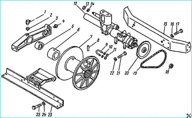
Disconnect the cable from the winch drum by unscrewing the nuts 11 (Fig. 2) securing the bracket, and remove the bracket 9
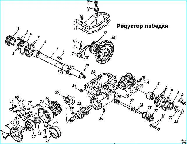
After removing the cable, drain the oil from the winch gearbox housing by unscrewing two plugs 34 (Fig. 3)
Disconnect the rear cardan shaft of the winch drive from the winch
Remove the protective coupling from the winch gearbox engagement fork rod cover
Moor the winch, unscrew the winch mounting bolts to the rear crossmember and the front crossmember mounting bolts to the frame
Guiding and supporting the winch with a crowbar, which must be rested against the rear crossmember, move the winch forward and turn it so that it passes between the frame side members.
Lower the winch and pull it out from under the car (this operation is performed by two people)
Note: when using a trolley, lower the trolley table or lift the rear of the vehicle and roll out the trolley
Installing the winch
Fill the winch gearbox with oil to the level of the inspection plug
Grab the winch with slings and move it under the vehicle
Moor the winch, lift it between the side members and turn it so as to install the front crossmember on the frame brackets
Screw in the winch mounting bolts to the rear crossmember and the front crossmember to the frame brackets
Put the protective sleeve on the winch gearbox engagement fork rod cover
Attach the rear propeller shaft to the winch
Install the cable
Before installing the cable, melt its ends or wrap them with wire
Before securing the cable, you need to make sure that the guide roller holder housing is in the extreme left position, while m the cable fastening bracket on the drum must be in the upper position
Push the cable forward
Secure the cable in the thimble with wedge 3 (Fig. 1), install the hook, pin and cotter it
Start the engine, fill the pneumatic drive of the brake systems with air. Engage the parking brake system
Set the transfer case control switch to the neutral position
Set the power take-off control switch to the "on" position
Engage first gear in the gearbox. We wind the cable, after three or four turns we tightly knock them down to the left flange.
After the fifth layer of winding, it is allowed to run one turn over another.
To bring it to the transport position, we hook the cable hook to the left towing hook, turn on the winch and first gear in the gearbox and smoothly tighten the cable (this operation must be done by two people)
Technical condition.
The brake should not heat up for 1-3 minutes above the temperature that can be withstood by hand. When heating, unscrew the nut 45 (Fig. 3) by two or three turns
We install two shields of the platform flooring
")

")
")
")
")
")
")
")