Analysis of failures in the power supply system
The main causes of failures in the power supply system are:
- - mechanical reasons (damage to live parts, their insulation and corrosion of contact surfaces, wear of mechanical parts);
- - deviations of external conditions from normal (increased temperature, humidity or dustiness of the environment);
- - exceeding the permissible electrical load in voltage or current.
In the power supply system, during vehicle operation, mechanical and electrical malfunctions occur, which cause disruption of the operation of electrical energy receivers of all other electrical equipment systems.
Mechanical faults are determined by external inspection and noise during operation.
Electrical faults are determined by readings from control devices.
During the operation of the vehicle, the following malfunctions of the power supply system occur.
All electrical energy receivers do not work
Symptoms of malfunction:
- - the lighting system lamps do not light;
- - the sound signal does not work;
- - the starter does not turn on;
- - the ammeter needle does not deviate towards the discharge when the devices are turned on.
Causes of the malfunction: the battery is faulty or completely discharged, the battery does not connect to the network
All receivers operate at low power when the engine is not running
Symptoms of malfunction:
- - The starter does not rotate;
- - lighting lamps burn with incomplete intensity;
- - the sound signal sounds weak;
Disruption of normal operation of all electrical energy receivers
Causes of malfunction:
- - The battery is very discharged;
- - increased resistance in the contact connections of the wire tips at the battery terminals, the car frame, at the terminals of the battery switch, starter traction relay, ammeter;
- - severe burning of the contact surfaces of the battery switch.
The battery is not charging
Symptoms of malfunction:
- while the engine is running at any crankshaft speed, the ammeter shows the discharge current.
Causes of malfunction:
- - Broken or low tension of the generator drive belt, open circuit connecting the generator and the battery (terminal “-1-” of the generator and positive terminal of the battery);
- - open circuit in the generator excitation circuit;
- - short circuit to the housing of the generator excitation circuit, the generator is faulty;
- - the voltage regulator is faulty.
Battery is not charging properly
Symptoms of malfunction:
- - the ammeter shows the low charging current when the battery is discharged at any engine speed;
- - when the headlights are turned on, the charging current sharply decreases or the ammeter shows a discharge current;
- - sharp fluctuation of the ammeter needle.
Causes of malfunction:
- - The voltage regulator is incorrectly adjusted;
- - low drive belt tension;
- - oiling or wear of the generator pulley;
- - loose contact in the charging circuit or generator excitation circuit.
A large fluctuation of the ammeter needle is observed when the slip rings are oiled and the generator brushes are stuck, when, due to vibration of the car engine, the contact between the brushes and the rotor rings is periodically broken and restored, in the connections of loose wire tips in the generator excitation circuit and in the charging current circuit.
The battery is being recharged
Symptoms of malfunction:
- - when the engine is running for a long time, the ammeter constantly shows the charging current, and its needle does not set to the zero scale division even with a fully charged battery;
- - with an increase in the crankshaft rotation speed, a significant increase in the strength of the charging current occurs, which causes the needle to deviate beyond the limit value of the ammeter scale;
- - strong gas formation in battery electrolyte;
- - rapid reduction of electrolyte level in batteries;
- - increasing the brightness of lighting lamps at medium and high engine speeds;
- - short service life of lighting lamps.
Causes of malfunction:
- - malfunction or incorrect adjustment of the voltage regulator;
- - short circuit between the wires connected to the terminals “-+-” and “Ш” of the generator.
In the event of a short circuit to the housing of terminal “Ш” of the generator or clamp Ш of the regulator, the voltage regulator will be switched off.
As a result, the generator voltage with increasing rotation speed can reach an excessively high value that is dangerous for lamps and other receivers electrical energy.
Vehicle power supply systems with alternating current generators and non-contact transistor voltage regulators (which is the system under consideration for KamAZ vehicles) are highly reliable in operation, subject to strict adherence to the rules of their operation.
In particular, it is necessary to monitor the condition and fastening of the wires at the terminals of the generator, voltage regulator and battery.
Operation of the generator with the “-+-” wire disconnected from the output leads, with an increase in rotation speed, to an increase in the voltage on the rectifier unit, which in turn can lead to its failure and damage to the voltage regulator.
An increase in generator voltage can also occur if the battery is disconnected by its switch while the generator is running.
The failure of the power transistor of the voltage regulator is caused by the short circuit of its terminals “-+-” and “Ш”.
A particular danger for an alternating current generator set is connecting the battery to it in reverse polarity. This leads to failure of the rectifier block diodes.
Building an optimal troubleshooting algorithm
Most of the known and currently used methods for constructing optimal diagnostic programs are based, as a rule, on taking into account statistical data on the reliability of system elements and the complexity of checks.
To implement these methods, it is necessary to have reliable data on the probabilities of failure of system elements and on the average time spent during implementation
various checks. To obtain such data, the labor intensity of checking each element of the system is first timed.
When timing, it should be taken into account that preparation for the test sometimes takes longer than the test itself.
This is due to the fact that access to individual devices of the power supply system on a KamAZ vehicle is difficult.
Therefore, when timing checks, it is necessary to take into account the time required to prepare for the check; the labor intensity of checking the following elements of the system is timed:
P0 - checking system performance using an ammeter
Start the engine, set the average crankshaft speed, turn on the headlights, and use the ammeter to draw a conclusion about the state (faulty or good) of the power supply system.
If the ammeter shows discharge current, it means that the generator set is faulty. Time to complete the check is about 1 minute;
P1 - checking the instrument switch and starter
Unscrew the nut securing the switch, unscrew the two left screws of the lower facing panel that blocks access to the switch terminals, and remove the instrument and starter switch.
Then connect one terminal of the control lamp to ground, and the second to the “VK” terminal of the switch. When checking, the key is in the first position. If the lamp does not light, this means that the result of test P1 is negative. Test time 2-5 minutes;
P2 - checking the wire connecting the “VK” terminal of the instrument switch and starter to the “+” terminal of the voltage regulator
Lift the front facing panel of the cab, connect the control lamp to the “+” terminal of the regulator, and the second clamp to the “ground” of the vehicle. The key must be in the first position. Test time 2-5 minutes;
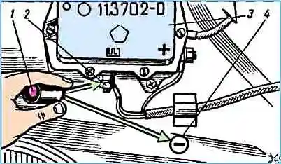
P3 - checking the voltage regulator
Lift the front facing panel of the cab, connect the control light to terminal “Ш” of the regulator, and the second clamp to the “ground” (Fig. 17) of the car.
In this case, the “ground” is turned on and the key is in the first position. Test time 2-5 minutes;
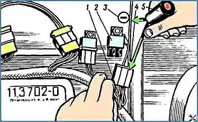
P4 - checking the connecting wire between terminal “Ш” of the voltage regulator and the field winding disconnect relay (Fig. 18)
Turn on the “ground”, put the key in the first position and lift the front facing panel of the cab, then connect one clamp of the control lamp to the “ground”, and the second to the supply socket of the connecting plug (the yellow wire goes to it). Test time 2-5 minutes;
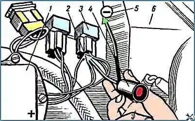
P5 - checking the field winding disconnect relay
Turn on the “ground”, put the key in the first position, lift the front facing panel of the cabin, connect the control lamp to the “ground” and to the “2V” terminal of the relay, fig. 19, middle terminal, yellow wire comes off).
Check time 2-5 minutes;
P6 - checking the wire from the relay to the generator
Raise the cab, connect the test lamp to ground and to terminal “Ш” of the generator (the yellow wire is suitable, Fig. 20).
For convenience, the plug with pin “Ш” can be removed from the generator socket.
Check time 3-5 minutes
During the test, “ground” is on, the key is in the first position;
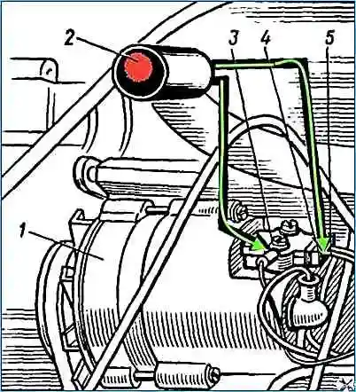
P7 - checking the generator
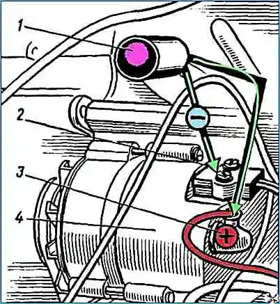
Raise the cab, connect the test lamp to ground and to the “+” terminal of the generator (the red wire comes off, Fig. 5). During the test, the engine should be running at medium speed. Test time 3-5 minutes;
P8 - checking the wires from the generator to the fuse for a current of 60 A
Start the engine, set the average frequency, connect the test lamp to “ground” and to the “1A” fuse (the red wire is suitable). Check time 1-2 minutes;
P9 - checking the fuse for a current of 60 A
Start the engine, set the crankshaft rotation speed to medium, then open the middle instrument panel and connect the warning lamp to ground and to terminal “1 G” of the fuse (red wire goes out). Check time 1-2 minutes.
If, when checking P1, the control lamp is on, then element X1 is serviceable and, accordingly, all the elements preceding it are serviceable.
If the control lamp does not light up, then the fault is in one of the elements up to X1 + 1.
When timing inspections, it was found that the time for conducting one inspection differs insignificantly from the time for conducting another inspection.
Therefore, an appropriate method for troubleshooting would be the midpoint method, according to which, during each test, the group of unchecked elements is divided into two subgroups containing approximately the same number of elements.
So, let's assume that the ammeter shows the discharge current when the engine is running (during the entire time the engine is running). Therefore, the generator set is faulty.
P5 is checked first. If the outcome of this check is negative, therefore, the fault must be sought among the elements X1..X5. We divide these elements into two more subgroups, performing check P3.
If the result of test P3 is positive, then by performing test P4, the faulty system element is determined.
If the result of test P4 is negative, it means that the fourth element is faulty - the wire from the voltage regulator to the field winding disconnect relay.
If test P4 is positive, the fifth element, the relay, is faulty.
When the result of check P3 is negative, check P2 should be performed. A positive outcome of test P2 indicates a malfunction of the third element - the voltage regulator.
If check P2 is negative, check P1 should be performed.
If the result of test P1 is negative, then the first element is faulty - the instrument and starter switch.
A positive outcome of test P1 indicates a malfunction of the second element - the wire from the switch to the voltage regulator.
If the first check P5 gave a positive result, incorrigibility should be sought among elements X6...X10.
Then check P8 should be performed, a positive outcome of which indicates that the fault should be sought among elements X9 and X10.
Therefore, check P9 is performed, a negative outcome of which indicates a malfunction of element X9, and positive - for a malfunction of element X10 (the ninth element is a 60 A fuse, the tenth is the wire from the fuse to the ammeter).
If the second check P8 gives a negative result, check P6 should be performed.
A negative result of this test indicates a malfunction of element X6.
After a positive outcome of test P6, it is necessary to perform test P7, a negative outcome of which indicates a malfunction of the seventh element - the generator, a positive outcome - a malfunction of the eighth element - the wire from the generator to the fuse.
Thus, we obtain an algorithm for troubleshooting in the power supply system, thanks to which, to find a faulty element of the system, it is enough to perform four checks instead of the possible ten.
- X1 – instrument and starter switch
- X2 – wire from the switch to the voltage regulator
- X3 – voltage regulator
- X4 - wire from the voltage regulator to the excitation winding disconnect relay
- X5 – relay
- X6 – wire from relay to generator
- X7 – generator
- X8 - wire from the generator to the fuse.
- X9 – 60A fuse
- X10 – wire from fuse to ammeter
")

")
")
")
")
")
")
")