The external and internal lighting system (Fig. 1) is designed to ensure vehicle safety, as well as illumination of the driver’s workplace
The external and internal lighting system of a vehicle includes headlights, fog lights, headlights, rear lights, engine compartment lamp, glove compartment and bed lamps, sockets with instrument lighting lamps, cabin lamps, portable lamp.
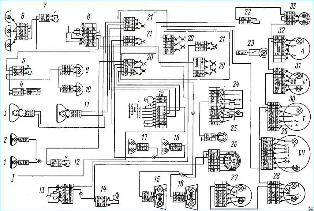
Electrical diagram of the external and internal lighting system: 1, 2 - right and left fog lights; 3.11 - right and left headlights; 4 - glove compartment lamp; 5 - lamp switch; 6 - road train lights; 7 - switch for road train lights; 8 - heater motor relay; 9,10 - cabin lamps left and right; 12 - fog lamp switch; 13 - brake signal relay; 14 - trailer solenoid valve switch; 15,16 - rear lights right and left; 17,18 - front right and left lights; 19 - combined light switch; 20 - fuse 13.3722 (7.5 A); 21 - fuse PR-310 (10 A); 22 - instrument lighting switch; 23 - engine compartment lamp; 24 - hazard warning light switch; 25 - portable lamp socket; 26 - seven-pin socket; 27 - oil pressure indicator; 28 - fuel level indicator; 29 - speedometer; 30 - tachometer; 31 - coolant temperature indicator; 32 ammeter; 33 - pressure gauge; 1-to instrument and starter switch
The connection of all consumers to the power source is made according to a single-wire circuit, with the exception of the ceiling lamp 4 of the glove box, the negative terminal of which is connected to the fuse panel.
The low and high beam of headlights 3 and 11, fog lights 1 and 2 and side lights are switched on using a combination switch 19 directly from the power source through an ammeter.
The circuits of the low beam headlights and fog lights are protected by thermobimetallic fuses PRZ 10 installed on the fuse panel.
The main beam headlight circuit is protected by a separate fuse of the same type.
The circuit of side lights and instrument lighting lamps is protected by an automatic thermobimetallic fuse type 13.3722.
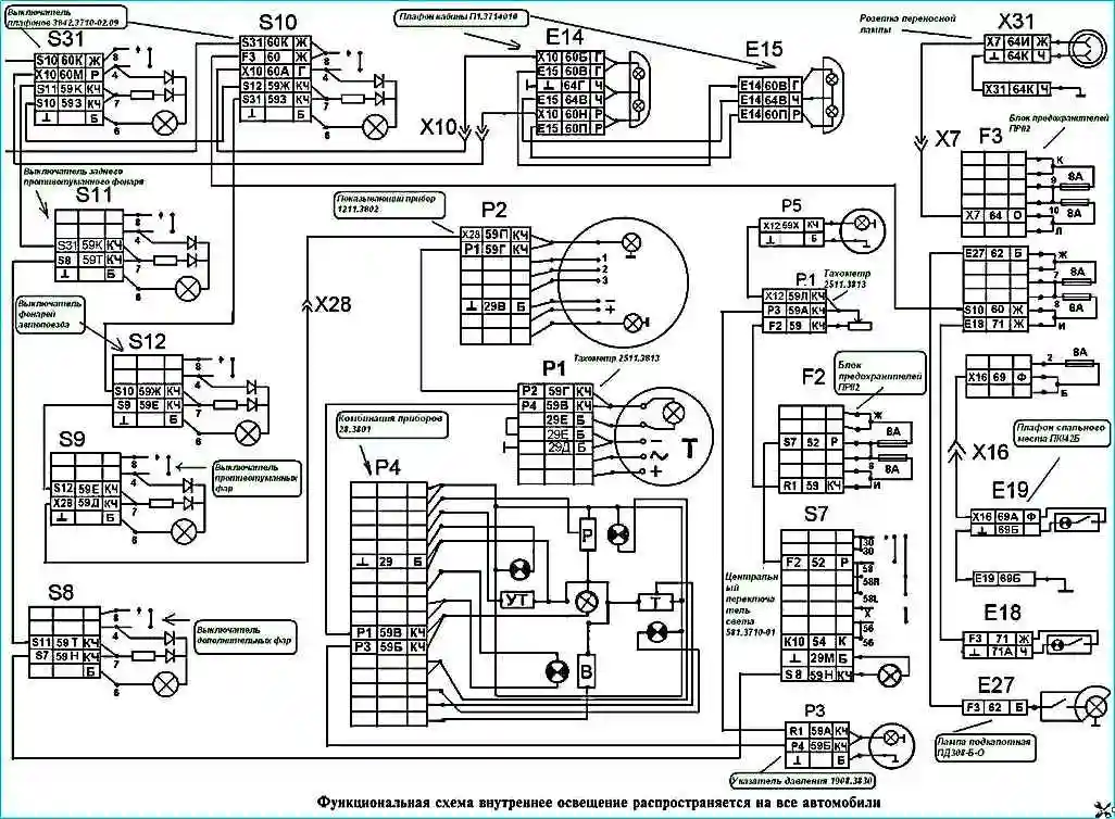
Functional diagram of interior lighting
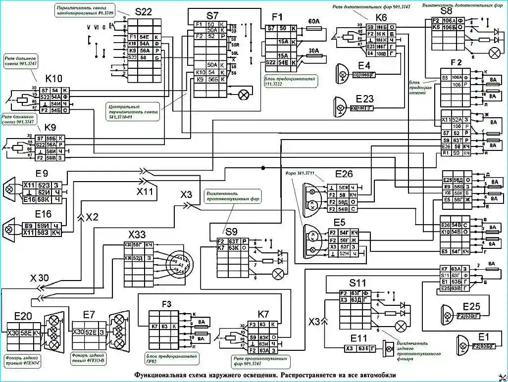
Functional diagram of outdoor lighting