The engine starting system of a KamAZ vehicle can be in three alternative states: serviceable, operational and faulty (failure)
If in good condition, the starting system ensures the engine starts, and the condition of all devices meets the requirements of the technical specifications.
When in working order, the system ensures reliable engine starting, but the technical condition of some devices does not meet the technical conditions.
If there is a malfunction (failure), starting the engine is impossible due to a malfunction of one or more system devices.
We will not consider the serviceable state of the system, since we are not tasked with determining the trouble-free operation period of the system by the number of starts or by the mileage of the car.
To perform most tasks, it is enough to have the system in working order, when the system ensures reliable engine starting.
Therefore, first of all, we will consider system failure and possible malfunctions, and indicate ways to quickly identify and eliminate them.
The system consists of seven devices, each of which affects the operation of the entire system.
Consequently, in order to optimize the troubleshooting process, it is necessary to time each test and evaluate its impact on the performance of the starting system:
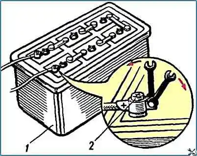
Checking batteries
Remove the cover from the battery socket.
By external inspection, check the condition of the terminals of the tips and the tightness of their fastening on the pole terminals (Fig. 1).
The degree of discharge of the battery should be determined by the density of the electrolyte. Check time is about 5 minutes;
Checking for voltage on the ammeter
Unscrew the bolts securing the instrument panel and tilt the panel towards you or place it on the steering column.
In this case, free access to the ammeter leads is available.
Connect a test light in series to the input and output of the ammeter.
If the light on the “+” of the ammeter is on, then the circuit up to the ammeter is working, and vice versa.
Then check the “-” ammeter. If the control lamp is on, it means that current is passing through the ammeter, and faults should be looked for further along the circuit.
If the light does not light, then the ammeter is faulty. This test without replacing the ammeter takes up to 2 minutes;
Checking the instrument switch and starter
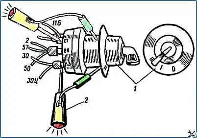
Before checking this device, it is necessary to carry out preparatory work to ensure access to the terminals.
To do this, you need to remove the guard of the electric motors of the cabin heating system, unscrew the nut securing the instrument switch and starter and remove the device from the panel, leaving it on the wires (Fig. 2).
Remove the red wire from the “AM” terminal and check the presence of voltage with a test lamp.
If the lamp is on, it means that the circuit to the instrument switch and starter is working.
Then you need to connect the red wire to the “AM” terminal, turn the key in the instrument and starter switch to the second position and check the “ST” terminal (green wire) with a light bulb.
If the lamp is on, it means that the instrument and starter switch is working.
Starter interlock relay
This relay is installed under the hinged fuse panel.
The relay is assembled on semiconductor devices and it is impossible to check it with a test lamp.
A special device is used for testing.
A malfunction of the starter interlock relay does not necessarily lead to loss of functionality of the starting system, so this test should not always be performed when troubleshooting;
Checking the starter relay
This relay is located under the hinged fuse panel.
Use a wire to connect the “+” from the ammeter to the “K” terminal of the relay. In this case, you should hear a click when the contacts are turned on.
In order to make sure that the contacts and relays are closed, it is necessary to connect a test lamp to terminal “C” of the starter activation relay (black wire).
If the lamp is on, it means the relay contacts are closing.
Checking the starter traction relay
Use a wire to connect the “+” from the batteries to the terminal that pulls in the starter relay windings.
If a click is heard, the relay is activated. The electric motor should rotate.
If the starter motor does not rotate I, then use a test lamp to check the presence of voltage on the contact bolt connected to the electric motor.
If the lamp is on, it means the starter traction relay is working normally.
Checking the starter motor
This check is the most time-consuming, since it is carried out (as a rule) with the starter removed. It takes 30 minutes to remove the starter and 25 minutes to diagnose.
Since the electric starting system has a small number of elements (only seven), the method of element-by-element testing is used, or sequentially dividing the system into two subsystems.
Possible engine starting malfunctions
Cause - solution
The engine does not start:
The starter does not turn the crankshaft or turns it very slowly
- - check the state of charge and serviceability of the batteries and, if necessary, charge or replace them;
- - check the contacts in the starter power circuit; if necessary, clean and tighten the wire terminals;
- - check the condition of the contacts of the starter relay, if there is burnt, clean the contacts;
- - check the contact connections on the battery, clean if necessary;
- - check the contact of the starter brushes with the commutator and the absence of sticking of the brushes in the brush holders; if necessary, wipe and clean the commutator, clean the side edges of the brushes, replace worn brushes with new ones or replace serviceable brush springs;
- - if it is impossible to eliminate the defect, replace the starter
The starter does not work; when it is turned on, the headlights do not dim
- - open circuit or wiring fault - Check the starter circuit and eliminate the fault;
- - lack of contact between the brushes and the commutators – Wipe the commutator with a cloth soaked in gasoline or clean the commutator with glass sandpaper. Check that the brushes are not stuck in the brush holders. Check the condition of the brush springs and replace them if they are faulty;
- - broken connections inside the starter - Check and eliminate defects or replace the starter;
- - malfunction in the starter relay circuit – Check the relay circuit and eliminate the malfunction
The starter rotates at high speed, but does not turn the crankshaft
- - breakage of the flywheel ring teeth - Replace the flywheel ring;
- - starter lever is bent – Correct the lever by straightening;
- - the finger of the starter lever is broken - Replace the lever with a new one
The starter relay works intermittently (turns on the starter and then turns it off)
- break in the holding winding - Replace the relay
The starter drive gear does not systematically engage with the flywheel ring during normal relay operation
- - the ends of the teeth of the flywheel ring or starter gear are heavily clogged - Replace the faulty flywheel ring or starter gear;
- - the starter relay adjustment is broken – Adjust the starter relay;
- - jamming of the starter gear on the shaft due to lack of or poor quality lubrication – Clean off dirt and lubricate with grease
The ammeter shows the discharge current at rated engine speed
- - slipping of the generator drive belts - adjust the belt tension, making sure that the generator bearings are in good condition;
- - the ammeter is faulty - Check and, if necessary, replace the ammeter;
- - electrical wiring fault - Use the indicator light to find the damage and eliminate the fault;
- - there is no contact between the brushes and the slip rings of the generator – Check the condition of the working surface of the slip rings, if necessary, wipe with a cloth soaked in gasoline; If dirt cannot be removed, clean the rings with glass sandpaper and wipe with a napkin. Check that the guide brushes are not jammed, if necessary, remove the brush holder, remove the brushes and clean them of brush dust;
- - the voltage regulator is faulty - Replace the voltage regulator;
- - phase loss, short to ground or interturn short circuit in the stator winding - Replace the stator;
- - open or poor contact in the generator excitation circuit - Check the integrity of the excitation circuit, brush assembly, soldering condition of the excitation winding to the rings, condition of the wiring, if necessary, replace faulty parts
High charging current (ammeter goes off scale), battery “boils”
- - the voltage regulator is faulty - Replace the voltage regulator;
- - short circuit of terminal “Ш” (shunt wire) of the generator to ground – Eliminate the short circuit
")

")
")
")
")
")
")
")