The moisture separator is designed to separate condensate from compressed air and automatically remove it from the feed part of the brake drive
The structure of the moisture separator is shown in the figure
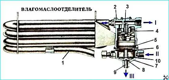
Compressed air from the compressor is fed through inlet II into the finned aluminum cooling tube (radiator) I, where it is constantly cooled by the flow of oncoming air.
Then the air passes through the centrifugal guide discs of the guide apparatus 4 through the hole of the hollow screw 3 in the housing 2 to the outlet I and then into the pneumatic brake drive.
The moisture released due to the thermodynamic effect, flowing through the filter 5, accumulates in the lower cover 7.
When the regulator is triggered, the pressure in the moisture separator drops, while the membrane 6 moves upward.
The condensate drain valve 8 opens, the accumulated mixture of water and oil is removed into the atmosphere through outlet III.
The direction of the compressed air flow is shown by arrows on housing 2.
Replacing the water separator
We replace the water separator in the event of the following faults:
- - loss of tightness, an external sign of which is a continuous air leak at the joints of the housing with the cover;
- - irreparable air leakage through the atmospheric outlet in filling mode;
- - cracks, mechanical damage to the water separator housing that disrupt its operation
To complete the task, you will need the following tools: wrenches 13x17, 22x24, 24x27
Removing the water separator
Lift the front panel of the cabin
With a 22 key, unscrew the union nuts of the pipelines
With a 27 key, unscrew the fittings with gaskets
Using 17 and 13 keys, unscrew the four bolts securing the bracket to the water separator
Installing the water separator
Install the water separator on the brackets by screwing in four bolts
Install the gaskets and screw in the fittings
Connect the pipelines by tightening the union nuts
Disassembling and assembling the water separator
Tools needed for the job: a vice, 10, 13 keys, a screwdriver, pliers, and a container for washing and lubricating
Disassembling the water separator
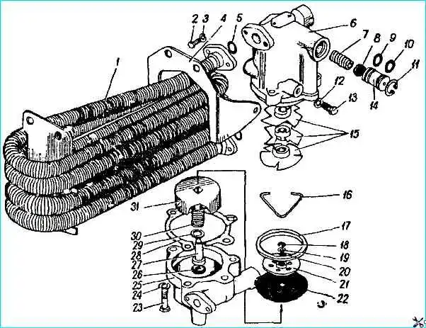
Using a 13 mm wrench, unscrew bolts 13 and disconnect bracket 4 from the water separator
Using a 10 mm wrench, unscrew bolts 2, disconnect pipe 1 from the water separator and remove ring 5
Using a 13 mm wrench, unscrew bolts 23 and disconnect cover 25 from housing 6, remove seal 28 and thrust ring 17
Remove piston 31 from cover and disassemble it: remove retaining ring 18, washer 19, disk 21, membrane 22, spring 30, sealing ring 29, valve 27.
Remove valve 26 from the spool, and extract ring 20 from disk 21
Remove retaining ring 11, valve 8, piston 14 with sealing rings 9, 10, spring 7
Remove stopper 16, guide disks 15 from housing 6
Wash the water separator parts in diesel fuel and blow them with compressed air
Assembling the water separator
Install guide disks 15 in housing 6 and secure them with stopper 16
Install housing 6 to the pressure regulator, spring 7, valve 8, piston 14 with sealing rings 9, 10 and secure with a retaining ring 11
Note: before installation, lubricate the working surface of piston 14 with Tsiatim-221 grease
On spool 27, install valve 26, ring 29, spring 30, piston 31.
On piston, install membrane 22, membrane disk 21 with ring 20, washer 19 and retaining ring 18
Install piston assembly, thrust ring 18 and seal in cover 25
Connect body 6 and cover 25 by tightening bolts 23
Connect pipe 1 to water separator by installing ring 5 and screwing in bolts 2
Attach bracket 4 to water separator, upno bolts 13
")

")
")
")
")
")
")
")