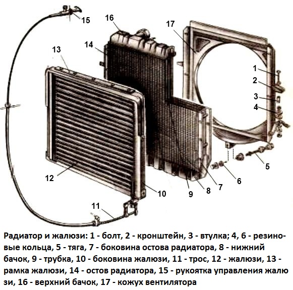
The tube-and-band type radiator is located in front of the engine. It consists of a heat-dissipating core (core) 14, upper 16 and lower 8 tanks and fasteners
Three rows of vertically arranged oval core tubes are soldered into the tanks.
To increase the heat-dissipating surface, the space between the tubes is filled with corrugated copper tape, located horizontally and soldered to the side surfaces of the tubes in kinks.
Steel side racks are soldered to the tanks, forming the radiator frame together with the bottom plate.
A pipe for supplying heated liquid from the heads of the engine block and removing steam to the expansion tank is soldered into the upper tank.
The lower tank is equipped with a pipe for draining cooled liquid from the radiator to the pump.

The radiator assembly with the fan shroud 17 is attached to the frame brackets through rubber rings 4.
Compression of the rubber rings is limited by spacers 3. Rod 5 keeps the radiator down from angular movements around the transverse axis.
Blinds 12 of the wing type regulate the intensity of the radiator blowing by the oncoming air flow. They are located in front of the radiator and consist of horizontal plates mounted pivotally in a frame, driven by handle 15, located under the instrument panel, on the right, near the steering column.
The drive handle is locked in various positions with a ball lock.
When the handle is pulled out, the plates, turning on hinges, reduce the oncoming air flow to the radiator.
The blinds are closed when the engine warms up and when driving, if the coolant temperature does not rise above 70 ° C.
The expansion tank compensates for the change in the volume of liquid when it expands due to an increase in temperature on a running engine, helps to remove air from the coolant and condense the steam entering it from the cooling system, creates liquid backwater when the liquid pump is running, improving its working conditions, and also allows you to control the filling level of the cooling system.
It is installed above the engine on the right side of the vehicle and is connected to the thermostat box, the upper radiator tank, the cooling cavity of the cylinder block and the cooling cavity of the air brake compressor head.

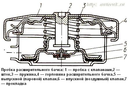
A plug 1 (Fig. 2.) with outlet 5 and inlet 6 valves is installed in the filler neck of the tank.
The exhaust (steam) valve protects the radiator and pipelines from destruction when the pressure in the system increases due to the expansion of the coolant with an increase in its temperature or the release of steam.
The spring 3 of the exhaust valve 5 is designed to create an excess pressure of up to 65 kPa in the cooling system.
The boiling point of the coolant at this pressure rises to approximately 113 ... 114 ° C.
The inlet valve 6 prevents the increase in vacuum in the system and communicates it with the atmosphere at a vacuum of 1 ... 13 kPa.
Thermostats with a solid filler and a direct valve stroke are designed to accelerate the warm-up of a cold engine and automatically maintain its optimal thermal regime when the car is moving.
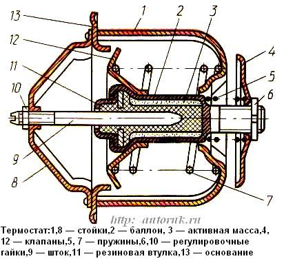
They are placed in box 16, fixed on the front end of the right cylinder block. On the base 13 of the thermostat (Fig. 3), racks 1, 8 are fixed, inside of which a cylinder 2 with an active mass and a rubber bushing 11 and valves 4, 12 with springs 5, 7 are placed.

When a cold engine warms up, the branch pipe connecting the cavities of the block with the radiator is closed by the radiator valve 12, the bypass valve 4 is open and provides fluid supply to the pump.
The liquid in this case circulates in a small circle bypassing the radiator, which speeds up the engine warm-up.
Heating the engine to a temperature of (80 ± 2)°C causes the active mass in the cylinder to melt, which leads to its displacement to the right; this opens valve 12 and closes valve 4.
The liquid begins to circulate partially and in a large circle with its cooling in the radiator. Full opening of valve 12 and closing of valve 4 occurs at a liquid temperature of (93 ± 2) °C, which ensures the circulation of liquid only through the radiator.
When the temperature of the liquid decreases, the volume of the active mass in the thermostat cylinder decreases and the spring 7, by moving valves 4, 12, it increases the circulation of fluid through the cylinder block while reducing its movement through the radiator.
The engine warms up and reaches its optimum operating mode faster.
Control over the thermal regime of the engine is carried out using instrumentation.
The coolant temperature gauge is located on the instrument panel and works in conjunction with a sensor installed in the wall of the thermostat box.
A liquid overheating warning light with a red light filter is built into the temperature gauge scale: the warning light sensor is installed in the engine piping.
When the coolant temperature is higher than (101 ± 3) ° C, the sensor is triggered and the signal lamp lights up.


