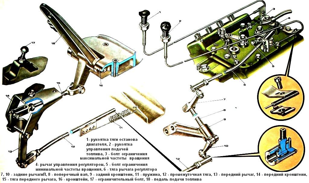
The fuel supply control drive (Fig. 1) consists of a pedal, rods, levers and transverse rollers
There is also a manual drive for fuel supply and engine stop.
The fuel control pedal 18 is connected to the speed control lever 4.
Hand levers mounted on the gear lever seal:
- - left 2 (to turn on the constant fuel supply) is connected by a flexible cable in a protective sheath to the control lever of the speed controller;
- - right 1 (to stop the engine) - with a cable with a stop lever, which is located on the cover of the speed controller.
The fuel system uses fuel lines of low (up to 2 MPa) and high (up to 20 MPa) pressures.
The first ones are designed to supply fuel from the tank through the appropriate filters to the low pressure pump, high pressure pump and remove excess fuel to the tank.
They are made from steel and plastic tubes and attached with hollow bolts through special tips; the contact surfaces of the tips are sealed on both sides with copper washers.
The high-pressure fuel lines connect the injectors and the high-pressure pump are made of steel tubes with an outer diameter of 7 mm and an inner diameter of 2 mm.
Internal surfaces are free of scale.
The pipelines have different lengths: three - 485 mm each, the other three - 516 mm each, two - 618 mm each.
Their ends, made by landing in the shape of a cone, are screwed with cap nuts and washers to the conical sockets of the fittings of the fuel pump section and injectors.
In order to avoid damage from vibration, the fuel lines are attached to the bearing parts with special brackets.


