Fuel is supplied to the burner under pressure in a finely atomized state
Fuel pressure is generated by a special pump
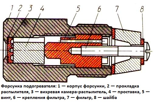
Fuel is sprayed by a nozzle (Fig. 1), which consists of a vortex spray chamber 3 in the form of a plate with tangential channels
The chamber through the spacer 4 is pressed by the screw 5 to the nozzle body. The seal between the nozzle and the swirl chamber is provided with a gasket 2.

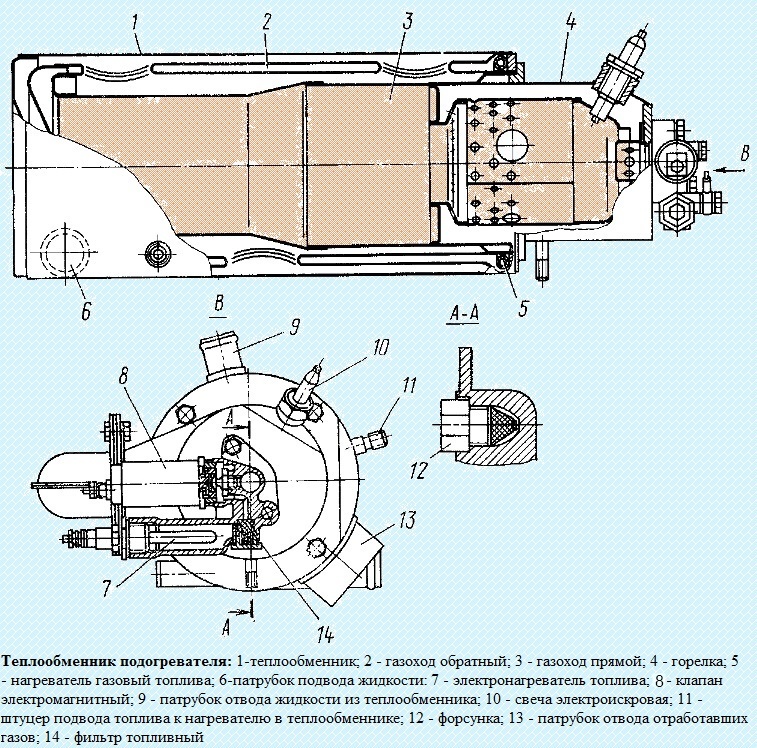
The nozzle is screwed into the solenoid fuel valve (Fig. 1), designed to remotely turn off or turn on the fuel supply for combustion in the heater.

The valve is opened by the electromagnetic field of the coil, and closed by a return spring.
In addition to the nozzle, an electric fuel heater and a fine fuel filter 14 are installed in the valve body.
This arrangement of heater elements in one unit is compact and easy to maintain.
Installation of an electric fuel heater directly into the valve body also provides heating of the body, which eliminates the possibility of freezing of the shut-off hemisphere in the presence of condensate, and also reduces the resistance of fuel filters in the event that paraffins fall out of the fuel under the influence of a negative temperature.
The whole assembly is mounted on the heater burner body.
The electric fuel heater is a pin candle, i.e. a spiral, closed by a casing. It is threaded into the solenoid valve body and sealed with a gasket.
The electric heater is designed to eliminate the negative impact of the increased viscosity of the fuel at its low temperature on the performance of the heater during ignition.
When the ambient temperature is above -30°C, it is possible to start the heater without using an electric fuel heater, which drastically reduces the power consumption of batteries.
In the steady operation of the heater after its start-up, heating of the fuel supplied to the nozzle is provided by the heater (see figure) from the heat of the exhaust gases at the outlet of the boiler return gas duct.
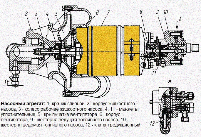
The pump unit is a device consisting of a fan (supercharger), fuel and liquid pumps driven by a single electric motor.
Fluid pump and fan are cast aluminum housing and mounted on one side of the motor, while the fuel pump is mounted on the opposite side.

The centrifugal type liquid pump is designed to circulate the coolant between the preheater and the engine cooling system.
Impeller 3 is mounted directly on the motor shaft 7 and secured with a nut.
On the fan side, the working cavity of the pump is sealed with a rubber cuff 4.
The liquid is supplied to the pump through the pipe on the pump cover, and is discharged through the pipe on the pump body.
The faucet 2 is designed to drain the liquid from its cavity.
A centrifugal fan supplies air to the heater burner.
Impeller 5 of the fan is mounted on the motor shaft on a key and secured with a nut.
The necessary clearance between the impeller and the fan housing is provided by a spacer sleeve installed between the motor bearing and the impeller hub.
The fuel gear pump supplies pressurized fuel to the heater injector.
The pump shaft on the motor side is sealed with a rubber collar 11.
The drive gear shaft 9 of the pump is connected to the motor shaft by an elastic coupling 8.
The performance of the fuel pump is regulated by the pressure reducing valve 12, which ensures the bypass of fuel from the pumps discharge cavity to the suction cavity.
Fuel is supplied to the gear pump by gravity from a special tank, which is installed on the fuel drain from the high pressure fuel pump (TNVD).
Such an installation provides automatic filling of the supply tank when the engine is running, while fuel already cleaned in the fine filter enters the tank, the fuel supply is maintained even if there are leaks in the suction line to the gear pump.
Final filtration of fuel from impurities is carried out by fine filters, installed in the solenoid valve body and on the nozzle.


