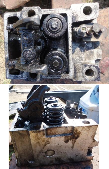
The cylinder heads are separate for each cylinder, made of aluminum alloy. They have water cavities communicating with the same cavities of the cylinder block, inlet and outlet channels, plug-in seats and valve guides.
The junction of the cylinder head with the block is sealed with two types of gaskets.
One rubber gasket seals the head along the contour and cavities for the gas distribution mechanism rods, the tightness of the water bypass and steam outlet channels is ensured by separate rubber rings. inserted into the holes of the head.

The gas joint between the cylinder head and the cylinder liner is sealed with ring 7, which is in direct contact with the collar of the liner and seals the joint due to the high precision of the lead coating.
The valve mechanism and the nozzle are located in the cylinder heads.
The valve mechanism of the head is closed with an aluminum cover sealed with a gasket. Cast iron seats and sintered valve guides are bored after being pressed into the head.
On the side of the mating plane of each head, two holes are made, into which, when assembling the engine, locking pins pressed into the block enter.
Each head is secured to the cylinder block with four bolts.
To avoid leakage of the gas joint, the bolts are tightened in a cross pattern, in three steps.
The inlet and outlet ports are located on opposite sides of the head. When looking at the engine from the side, the intake valves of the heads are on the right, and the exhaust valves are on the left.
The inlet channel has a tangential profile, which ensures the vortex movement of air in the cylinder, improving mixture formation and accelerating the combustion process of the injected fuel.
The socket for the nozzle is located on the side of the exhaust valve at an angle to the axis of the cylinder.
Removing heads and replacing cylinder gaskets
Cylinder head gaskets are replaced if there is a leak in the connection between the cylinder head and the cylinder block
Rupture and burnt gaskets cause coolant and oil to leak at the junction of the cylinder head and block
Removing cylinder head gaskets
We prepare the car and disconnect the electrical wires from the battery terminals
Draining the coolant from the engine cooling system
We unscrew the bolts and remove the cover of the front hatch of the clutch housing
Raise the front of the car and place a stand under the frame cross member
Remove the intake manifolds and disconnect the pipelines
We unscrew the bolts and disconnect the flange of the thermostat box
We unscrew the bolts of the water pipes on the right and left sides and separate the pipes from the cylinder heads
Loosen the exhaust manifold bolts

We unscrew the bolts 10 (according to the figure) securing the cylinder head covers and remove the covers 11 with gaskets 5
We unscrew the nuts 9 fastening the racks of the rocker arms 6, remove the racks assembled with the rocker arms and clamps of the rocker arms and the rods 4 of the pushers (we use a key of 17, a chisel, a hammer).
Note: performed only on the heads of the fourth and eighth cylinders
Using a 19 head with a knob, loosen the cylinder head bolts in the sequence shown in the diagram, then unscrew them, remove the heads and mark them by cylinder numbers
Note: do not place the head with the mating surface on the stand to avoid damaging the injector nozzles
Remove the push rods
Remove the cylinder head gaskets: sealing (along the perimeter of the head) and steel (for a gas joint with a steel gasket)
We clean the mating surfaces of the cylinder heads and cylinder block from carbon deposits and scale
Installing cylinder head gaskets
Installing cylinder head seals on the block
We install new steel head gaskets on the upper end of the sleeves (for a gas joint with a steel gasket)
Note: lubricate steel gaskets with engine oil before installation
We install the rods 4 of the pushers 2, screw in the adjusting screws 8 with a torque of 33.3-41.1 Nm (3.4-4.2 kgcm)
We install the heads of 12 cylinders, centering them on the pins of the block, while making sure that the adjusting screws for thermal gaps "A" entered the tips of the rods
We tighten the head mounting bolts in three steps in the sequence shown in the figure

- First pass - 39.2-49.1 Nm (4-5 kgcm);
- Second stroke - 117.7-147.2 Nm (12-15 kgcm);
- Third stroke - 156.9-176.5 Nm (16-18 kgcm)
Note: before screwing in, lubricate the bolt threads with USSA graphite grease mixed with engine oil to a creamy state, clean the threaded holes in the block from dirt and liquid
We install the rocker arms assembly with rocker arms 6 and rocker arm clamps on the cylinder heads, tighten the nuts 9 for fastening the racks with a torque of 41-51.9 Nm (4.2-4.5 kgcm)

Using I801.14.000 we adjust the thermal gaps "A" in the valve mechanism
The clearance for the intake valve is 0.25-0.30 mm, for the exhaust valve 0.35-0.40 mm
Install the cover of the front hatch of the clutch housing
We screw in the bolts of the exhaust manifolds
We install 11 heads with gaskets 5 on the heads of 12 cylinders and fix them with bolts 10 with flat washers
We install water pipe gaskets on the heads, water pipes assembled with a connecting pipe, tighten with bolts with flat and spring washers
We attach the flange of the thermostat box with bolts with flat and spring washers
Install the intake manifolds and connect the pipes to the heads
Remove the stand from under the front of the car
Fill coolant
Lowering the cab
Connect the wires to the batteries
We start the engine and check the operation of the gas distribution mechanism, the tightness of the cooling system and engine fuel supply, the power steering system
Not allowed: knocking in the gas distribution mechanism, leakage of coolant, oil and fuel
")

")
")
")
")
")
")
")