The pressure limiting valve serves to reduce the air pressure in the brake chambers of the front axle during low-intensity braking, which improves stability and controllability (especially on slippery roads), as well as to quickly release air from the brake chambers when releasing the brakes
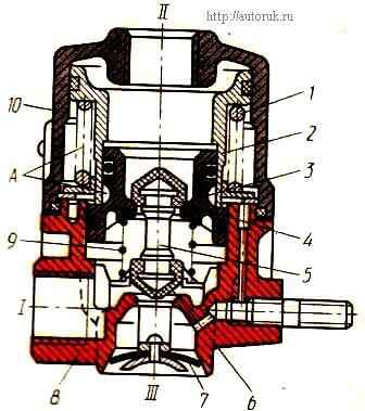
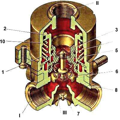
The pressure limiting valve consists of a housing 8, a housing cover 10, large 2 and small 3 pistons, a rod 5 with upper 4 and lower 6 valves and piston springs.
Valve terminal II is connected to the lower section of the brake valve, terminal “I” is connected to the brake chambers of the front wheels, terminal “III” and cavity “A” are connected to the atmosphere.
In the initial position (without braking), terminal “II” is connected to the atmosphere through the brake valve.
Large piston 2 takes the upper position under the action of spring 1.
The brake chambers of the front wheels are connected to the atmosphere through terminals “I” and “III” of the valve.
The pressure in the cavities above and below the small piston is the same and equal to atmospheric pressure, small piston 3 is in equilibrium.
The upper valve 4, under the action of the spring 9, is pressed against the seat of the small piston and separates the pressure limiting valve into two cavities.
When braking, compressed air coming from the brake valve to terminal “II” acts on the upper end of the small piston 3 and moves it down together with the double valve.
In this case, first valve 6 closes the hole, separating terminals “I” and “III”, and then, with further movement, piston 3 compresses spring 9 and lifts valve 4 from the piston seat, communicating terminals “I” and “II”.
Compressed air is supplied to the brake chambers of the front wheels until the pressure on the lower end of piston 3 is balanced by the air pressure acting on the upper end, and valve 4 closes.
Since the area of the lower end of piston 3 is larger than the area of the upper end, the pressure corresponding to the ratio of the areas of the piston ends is set in terminal “I”, i.e. 1.75:1.
This ratio is maintained when the pressure in terminal “II” increases to 350 kPa.
If the pressure in terminal “II” becomes more than 350 kPa, which corresponds to the force of the balancing spring 1, piston 2 is activated, which also begins to move downward, increasing the force acting on the upper end of piston 3.
With a further increase in pressure in terminal “II”, its difference in terminals “II” to “I” becomes less and less, and upon reaching 600 kPa it equalizes.
Thus, a follow-up action is carried out throughout the entire range of operation of the pressure limitation valve.
When the pressure at port “II” decreases (the brake valve is released), pistons 2 and 3 move upward, inlet valve 4 closes, and exhaust valve 6, starting to move with the piston, opens and compressed air from the brake chambers escapes into the atmosphere through the outlet "III".
In this case, the pressure relief valve acts as a quick release valve.
")

")
")
")
")
")
")
")