Check the condition and operation of the platform lift limiting valve.
Fasten the lift limiting valve to the subframe crossmember bracket. The valve stem must not be bent.
The adjusting screw must be securely locked with a lock nut.
To adjust the platform lift angle of the KAMAZ-55111 dump truck, do the following:
- - unscrew the lock nut of the adjusting screw of the lift limiting valve;
- - screw the adjusting screw into the stem until it stops; raise the platform to a position where the locking pins freely enter the holes in the subframe brackets, and lock the platform in this position with the locking pins;
- - unscrew the adjusting screw from the valve stem until it stops in the hydraulic cylinder body and lock it with a lock nut.
Unlock the platform, lower it and raise it again.
Make sure that the platform stops lifting when the axis of the locking pins coincides with the axes of the holes in the brackets subframe.
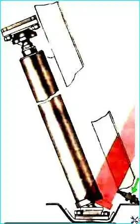
To adjust the platform lift angle of the dump truck mod. 55102, perform the following operations:
- - lift the platform to the left at an angle of 48-50° and install a technological stop under it;
- - unscrew the lock nut of the adjusting bolt and unscrew or screw the bolt so that the lift angle is equal to the specified one, then tighten the lock nut; adjust the platform lift value to the right in the same way;
- - lower and raise the platform again: make sure that its lift is limited to an angle of 48-50°.
It is necessary to pay attention to the position of the lever with the platform lowered.
It should be pressed by the spring against the adjusting screw of the limiting valve. Otherwise, the spring tension should be adjusted.
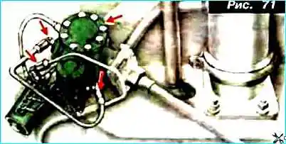
Fig. 2. Check the condition and operation of the platform lift control valve.
Air leaks (check by ear) and oil leaks are not allowed.
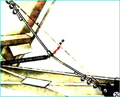
Fig. 3. Check the deflection of the platform lifting safety cable.
The deflection should be 35-50 mm.
Adjust the deflection by loosening the cable clamps.
The cable should not have any strand breaks.
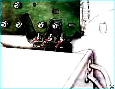
Fig. 4. Fasten the front subframe brackets.
Tightening torque of the nuts is 79-98 Nm (8-10 kgf m).
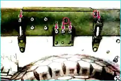
Fig. 5. Fasten the subframe tie bolts.
Tightening torques for nuts 1 of the M12 subframe mounting bolts are 79-98 Nm (8-10 kgf m), nuts 2 of the M16 subframe tie bolts are 176-216 Nm (18-22 kgf m), and bolts M14 are 137-157 Nm (14-16 kgf m).
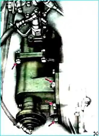
Fig. 6. Fasten the power take-off box and oil pump.
The tightening torque of the bolts is 39-49 Nm (4-5 kgf-m).
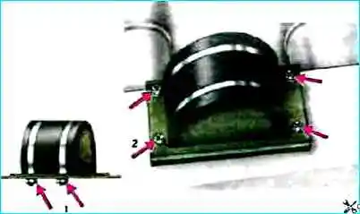
Fig. 7. Fasten the shock absorber catcher.
Tightening torque of nuts 1 of clamps — 54-62 Nm (5.5-63 kgf-m).
Tightening torque of nuts 2 of bolts — 137-147 Nm (14-15 kgf-m).
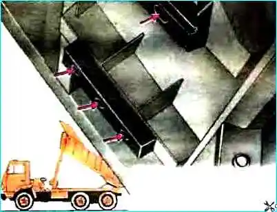
Fig. 8. Secure the platform shock absorbers.
Tightening torque of nuts and bolts — 44-53 Nm (45-54 kgf-m).
Drain the sediment from the hydraulic cylinder of the platform lifting mechanism (for the KAMAZ-55102 vehicle).
Changing the oil in the hydraulic system of the platform lifting mechanism.
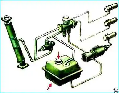
The oil level in the tank is checked with the platform lowered using an indicator mounted in the tank cap. The level should be between the "H" and "B" marks on the indicator.
To fill the hydraulic system, you should:
- - unscrew the oil tank filler cap, remove, wash and reinstall the mesh filter;
- - fill with oil up to the B mark on the oil level indicator;
- - raise and lower the platform 3-4 times at an average rotation speed crankshaft of the engine (1100-1300 rpm) to remove air from the system;
- - check the oil level, top up to the "B" mark if necessary.
Possible malfunctions of the platform lifting and lowering mechanism and how to eliminate them
Malfunction
- Cause of malfunction
Remedy
Power take-off does not engage
- Open circuit of the solenoid valve
Remove the open circuit
- Seizure of the solenoid valve stem
Disassemble the solenoid valve, eliminate the cause of the jamming
Power take-off does not turn off
- Seizure of the solenoid valve stem
Disassemble solenoid valve, eliminate the cause of jamming
The platform is not held in the raised position when the control valve switch is set to the neutral position
- Foreign particles are under the control valve valves
Turn on the lifting mechanism several times and bleed the system at an average engine crankshaft speed.
If this does not eliminate the malfunction, remove the valve or tap and wash them.
Change the oil
- Solenoid valve stem is jammed
Disassemble the solenoid valve, eliminate the cause of jamming
Platform lifting is not limited
- Violation of the platform lifting angle adjustment
Adjust the lifting angle
Platform does not lower
- Open circuit control crane solenoid valves
Remove breakage
- Solenoid valve stems are jammed
Disassemble solenoid valves, eliminate cause of jamming
- Rupture of control crane pneumatic chamber membrane
Replace membrane
- Air leak
Tighten pneumatic line connections
Slow or uneven platform lift
- Oil leak through drain valve in control crane or lift limit valve as a result of foreign particles getting under valve
Turn on platform lift mechanism several times and remove air from system at medium engine crankshaft speed.
If fault persists, remove crane or valve and wash them. Change oil
- Reduced pump flow
Replace pump
- Inconsistency of the season of operation of the oil filled with the hydraulic system
Fill with the appropriate oil
- Air entering the hydraulic system
Check the tightness of the suction line.
Eliminate air leaks.
Remove air from the hydraulic system by raising and lowering the platform 3-4 times
The platform does not rise
- Excessive platform load
Partially unload the platform manually
- Open circuit in the control valve solenoid valve circuit
Eliminate the open circuit
- Air leak
Tighten the connections pneumatic lines
- Seizure of the solenoid valve stems
Disassemble the solenoid valves, eliminate the cause of the seizure
- Rupture of the control valve pneumatic chamber membrane
Replace the membrane
Oil leakage from the holes connecting the control valve and the distributor with the environment
- Increased wear of the tappet seals in the valve or the valve seals in the distributor
Replace the tappet or valve seals
Oil leakage through the hydraulic cylinder seals
- Wear or destruction of the sealing cuffs
Replace the sealing cuffs
")

")
")
")
")
")
")
")