As the compressor operates, the cylinder-piston group wears out and the tightness of the valves is compromised
In case of these malfunctions, the filling time of the pneumatic system (before extinguishing the warning lights) at an engine speed of 2200 rpm exceeds that established by the technical specifications, i.e. 8 minutes, or the compressor does not develop the specified pressure at all, 7-7.5 kgf /cm 2
In addition, wear of the cylinder-piston group leads to the absorption of oil mist from the compressor crankcase into the cylinders, and then the oil along with the air goes into the pneumatic system.
After filling the pneumatic system with air, the unloading valve opens in the pressure regulator, the oil along with the air is thrown out and settles on the regulator and frame.
It should be noted here that oil consumption through the compressor increases due to contamination of the engine air filter.
The fact is that the compressor sucks in filtered air from the engine intake manifold.
As the filter gets dirty, the vacuum in the intake manifold increases, and the compressor, even with a working piston group, sucks in oil mist from the crankcase, and then throws it into the pneumatic drive during the exhaust stroke.
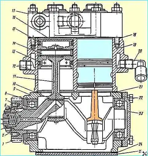
Leaks in cylinder head gasket 18, internal cracks in the head or block lead to liquid from the cooling system being sucked into the cylinders and then, together with air, going into the pneumatic drive.
The coolant level in the expansion tank drops, and the liquid in it bubbles.
This happens because the piston during the compression stroke pushes air into the compressor cooling jacket, and then the air and liquid merge into the expansion tank.
There is another dangerous consequence of the considered malfunctions.
The liquid that has entered the compressor cylinder seeps into the compressor crankcase through the gaps between the cylinder, piston and rings, and from it flows into the engine oil pan.
If liquid gets into the oil, when searching for a leak, you must also keep in mind the compressor.
Otherwise, due to a faulty compressor, a serviceable engine may be mistakenly sent for repair, and the faulty compressor may be reinstalled on another serviceable engine.
Oil for lubricating the compressor is supplied from the central oil channel of the engine to the mechanical seal 4 installed in the crankshaft.
The seal is pressed to the flywheel housing by spring 5.
If the mechanical seal is significantly worn, as well as the spring is broken, the oil, bypassing the compressor, directly flows onto the timing gear block and then into the engine sump.
This malfunction can cause failure of not only the compressor (seizing due to lack of lubrication), but also the engine (cranking of the crankshaft liners due to oil starvation).
Incomplete opening of the exhaust valves leads to overheating of the air at the compressor outlet.
Disassembling the compressor
Disassembly of the compressor mounted on the stand begins with removing the cylinder head. Then the intake valves, their guides and seats are removed from the cylinder block sockets.
Holding the block head in a vice, unscrew the injection valve plugs, remove the valves, seats and sealing gaskets.
Bending the tendril of the lock washer 2 and unscrewing the nut 3 securing the crankshaft drive gear, remove the lock washer.
Then, using a device, the compressor drive gear is removed and key 6 is removed from the crankshaft groove.
In order to remove the mechanical seal and spring from the crankshaft, you must first remove the thrust ring from the crankshaft.
Turning the compressor on the stand with the bottom cover up, unscrew the fastening bolts and remove the bottom cover with gasket 24.
Then you need to unscrew and unscrew the nut securing the connecting rod covers, remove the covers.
By tapping the end of the lower head of the connecting rod with the handle of a hammer, remove the piston with connecting rod.
Having removed the liners, you need to connect the covers and connecting rods in pairs with bolts so as not to confuse them in the future. Connecting rod with to The lid is processed as an assembly, so they are replaced only in pairs.
Turning the compressor with the cylinder block up, unscrew the nuts securing the block to the crankcase and remove the cylinder block with the 21 oil deflector plates.
After this, unscrew the bolts securing the rear crankcase cover 23 and remove the cover.
Before pressing the crankshaft out of the crankcase, the thrust ring of the main bearing installed on the drive gear side is removed.
Holding the connecting rod in a vice, remove the compression oil rings from the piston and remove the thrust ring of the piston pin.
After pressing out piston pin 14, disconnect the piston from the connecting rod, and then press out the bushing from the upper head of the connecting rod.
Defects of compressor parts
If defects are detected, parts with cracks, chips, burrs, scratches on working surfaces, and other mechanical damage are subject to rejection.
Table 1:
Size - Cylinder diameter, mm - Marking
- Nominal - 60+0.03 - 0;
- First repair - 60.4+0.03 - +0.4;
- Second repair - 60.8+0.03 - +0.8
If the inner surface of the cylinders is worn by more than 0.02 mm, it is necessary to bore the cylinders to the repair size (Table 1).
The seat diameter under the intake valve seat must not exceed 17.027 mm.
The diameter of the ball bearings in the compressor crankcase must be no more than 72.05 mm.
With a larger diameter, an interference fit of the bearing is not ensured.
The non-flatness of the contact surface of the compressor head to the cylinder block should be no more than 0.1 mm.
Risks and traces of wear on the surface of the discharge valve seats are eliminated by grinding and lapping of the valves.
The diameter of the hole for installing the discharge valve must be no more than 28.8 mm.
Table 2:
Size - Diameter of connecting rod journals, mm - Marking
- Nominal - 28.5-0.021 - 0;
- First repair - 28.2-0.021 - -0.3;
- Second repair - 27.9-0.021 - -0.6
The diameter of the crankshaft for ball bearings and gears must be at least 35 mm, for the mechanical seal no more than 25.05 mm, and the width of the keyway no more than 5.02 mm.
When the connecting rod journals wear out, they must be ground to the next repair size (table).
Table 3:
Group - Diameter of hole for pin in bushing, mm - Marking color
- I - 12.507-12.504 - white;
- II - 12,504-12,501 - green;
- III - 12.501-12.498 - blue;
- IV - 12,498-12,496 - red
The non-parallelism of the axes of the holes in the upper and lower heads of the connecting rod (bending) over a length of 100 mm should be no more than 0.1 mm.
The skew of the axes of the holes of the upper and lower heads (twisting) over a length of 100 mm should be no more than 0.15 mm.
The diameter of the lower head of the connecting rod must be no more than 32.02 mm, and the diameter of the bushing of the upper head must not be more than 12.507 mm.
If the upper head bushing is loose, it must be replaced.
When replacing the bushing, you must drill an lubrication hole and rotate the bushing to the nominal size.
Connecting rods are divided into groups at 0.003 mm intervals according to the smaller hole diameter and are marked with paint (table).
Table 4
Size - Piston diameter at the skirt, mm - Piston diameter at the bottom, mm - marking:
- Nominal - 59.9-0.03 - 59.8-0.03 -;
- First repair - 60.3-0.03 - 60.2-0.095 - +0.4;
- Second repair - 60.7-0.06 - 60.6-0.195 - +0.8
The height of the discharge valve plug must be at least 31.1 mm.
The seat diameter of the seal is no less than 24.94 mm.
For the compressor drive gear, the tooth thickness along the chord of the pitch circle must be at least 4.2 mm, and along the width of the keyway no more than 5.15 mm.
Table 5
Group - Diameter of the hole for the pin in the piston boss (pin diameter) - marking color:
- I - 12,500-12,497 - white;
- II - 12,497-12,494 - green;
- III - 12,494-12,491 - blue;
- IV - 12,491-12,488 - red
Piston wear at the bottom and skirt is not allowed by more than 0.015 mm from the nominal or repair size (Table 5).
The repair size pistons are marked on the outer surface of the bottom.
The diameter of the hole in the piston boss for the pin is allowed no more than 12.5 mm.
According to the diameter of the hole in the boss, the pistons are divided into groups every 0.003 mm (Table 6).
The diameter of the piston pin must be at least 12.488 mm. Fingers are sorted into groups by diameter.
Dimensions and markings in groups correspond to the sizes and markings for pistons (see Table 6).
Wear of the liner by more than 0.01 mm from the nominal or repair size (Table 7) is not allowed.
Table 6
Size - Thickness, mm - Marking:
- Nominal - 1.75-0.013 -;
- First repair - 1.90-0.013 - -0.3;
- Second repair - 2,0.5-0.013 - -0.6
When checking, piston rings are installed in ring gauges.
The gap in the lock of the piston ring installed in the caliber must be within 0.2-0.6 mm.
Ring repair kits are marked with green paint; the diameters of the gauges for checking the rings are shown in the table.
Table 7
Size - Caliber diameter, mm - Ring markings:
- Nominal - 60 - not marked;
- First repair - 60.4 - One strip 10 mm wide;
- Second repair - 60.8 - Two strips 10 mm wide
Compressor assembly
Before assembling the compressor, you need to select:
- - in groups, piston pins to pistons and connecting rods with bushings pressed into them;
- - according to repair dimensions of pistons to cylinders;
- - according to repair dimensions, piston rings to pistons;
- - according to the repair dimensions of the crankshaft liners. When pressing the bushing into the upper head of the connecting rod, you must ensure that the hole in the bushing coincides with the oil channel in the connecting rod.
The piston pin must be matched to the holes in the piston bosses with a gap of 0.003 mm, and enter the piston holes under the action of light hammer blows.
The gap in the interface between the piston pin and the connecting rod bushing should be in the range of 0.004-0.010 mm. The finger should fit tightly into the hole of the sleeve using hand force.
Having previously lubricated the friction surfaces with engine oil, you need to install the connecting rod into the piston and, aligning the holes, press in the piston pin. The pin is fixed in the piston by thrust rings.
Rings are then installed on the piston.
Compression rings are installed on the piston with a stepped groove upward, the joints of adjacent rings should be directed in opposite directions.
The gap between the ring and the groove should be 0.035-0.09 mm.
Next you should assemble the compressor head. To do this, install the discharge valve seat gaskets into the head, screw in the valve seats, insert the discharge valves, springs and plug gaskets, screw in the discharge valve plugs.
The crankshaft assembly with bearings is installed in the compressor crankcase until it stops against the ring.
Then a key is installed in the groove of the crankshaft, a gear is mounted on the shaft and key, which is fixed on the shaft with a nut and a lock washer.
The spring and seal installed in the crankshaft are secured with a thrust ring.
After installing the seal, you need to check its mobility: when you press the end with your finger, the seal should move freely.
Having installed the compressor crankcase on the stand and selected a set of gaskets 22, attach the rear cover to the crankcase.
Then, installing plate reflector 21 on the crankcase, secure the cylinder block to it.
Turning the cylinder block with crankcase assembly on the stand with the crankcase facing up, blow compressed air through the cylinders and crankshaft.
Install liners of the same repair size as the crankshaft journals onto the connecting rod and into the connecting rod cover.
Having previously lubricated the surfaces of the cylinders, pistons and crankpins of the crankshaft with engine oil, install the pistons and connecting rods assemblies into the cylinders.
Then install the covers assemblies with liners on the crankshaft journals and tighten the fastening nuts with a torque of 1.6-1.8 kgm, secure the nuts.
Then check the ease of rotation of the crankshaft. The turning torque should not exceed 0.8 kgf m. Having previously lubricated the contact planes with nitro enamel, secure the bottom cover with a gasket to the crankcase.
Having pressed the intake valve seats into the cylinder block, install the guides and valves.
After installing the intake valve springs and gasket 18, secure the head to the cylinder block. Tighten the head fastening nuts evenly in two steps.
The final tightening torque of the nuts should be 1.2-1.6 kgm.
")

")
")
")
")
")
")
")