The oil pump (Fig. 1) is two-section, gear type, has a drive gear ratio of 1.075 from the crankshaft nose gear, attached to the lower plane of the crankcase
To ensure a lateral clearance between the teeth of gear 5 of the pump drive and the crankshaft gear equal to 0.15-0.35 mm, a steel gasket can be installed between the crankcase and the pump.
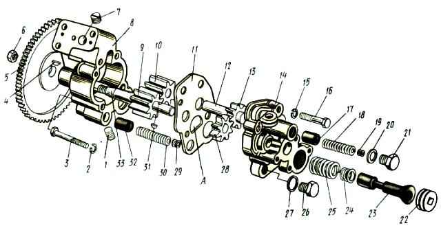
Cast iron housings 8 and 14 of the discharge and radiator sections, together with spacer 11, are tightened with bolts 3 and 16.
The required tightness of the connection is achieved without gaskets by carefully processing the joint planes.
High precision manufacturing of parts and the absence of gaskets make it possible to maintain clearances at the ends of the gear: 0.05-0.124 mm for the discharge section and 0.045-0.102 mm for the radiator sections, which prevents oil bypass from the discharge cavities to the suction cavities.
Drive gears 9 and 28 of both sections are mounted on a roller 33, which rotates in bronze bushings pressed into the holes of the housings.
Driven gears 10 and 13, together with bronze bushings pressed into them, rotate on a common axis 12.
Oil is supplied to the driven gear bushings through radial drillings in them between the gear teeth.
Oil from the sump through a fixed oil receiver with a strainer enters the suction cavity of the radiator section.
From here, a smaller part of the oil is pumped to the centrifuge, the larger part, through connecting hole “A” in the spacer, enters the suction cavity of the injection section and is fed into the lubrication system by its gears.
In the housing 14 of the radiator section of the oil pump there are threaded holes for plugs 21, 26 and 22 of safety valves and valve 23 of the lubrication system, and safety valve 17 is located in the housing of the radiator section, and safety valve 32 and valve 23 are located in the housing of the discharge section .
Safety valves of both sections are adjusted to an opening pressure of 850-950 kPa.
Valve 23 of the lubrication system begins to open when the oil pressure in the main line is equal to 400-450 kPa.
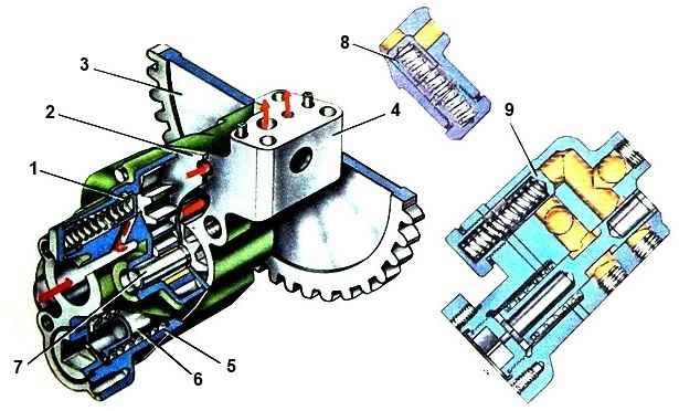
Oil pump: 1 – safety valve of the radiator section; 2 – spacer; 3 – drive gear; 4 – housing of the discharge section; 5 – body of the radiator section; 6 – lubrication system valve; 8 – safety valve of the radiator section; 9 – safety valve of the discharge section
")

")
")
")
")
")
")
")