The piston serves to sense gas pressure and transmit it through the piston pin to the connecting rod and crank of the crankshaft
It is subject to the greatest impact of mechanical and thermal loads
Since the piston moves back and forth, high cyclic inertial loads and significant friction forces between the side surface of the piston and the cylinder are additionally created.
At the same time, the piston acts as a sealing element of the crank mechanism and removes heat from the hot gases located in the space above the piston.
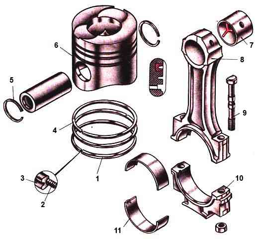
Piston 6 consists of a bottom, a sealing part and a guide part (skirt). On the inside of the skirt there are two massive bosses - bosses.
They are connected by ribs to the bottom, thereby increasing the strength of the piston.
The bosses have holes for the pin, in which annular grooves are machined for retaining rings 5.
The bottom, together with the sealing belt, forms the piston head.
On the outer surfaces of the head and skirt, grooves are machined for installing two compression rings and an oil scraper ring.
The upper part of the piston is called the sealing belt, since the piston rings measured here prevent gases from breaking through the gaps between the piston and the cylinder.
The lateral surface of the piston is stepped in height (the diameter of the piston head is less than the diameter of the skirt).
In cross section, the skirt has the shape of an ellipse, with the major axis of the ellipse located in a plane perpendicular to the axis of the finger.
This design of the piston ensures that the gap between the piston and the liner in the plane of movement of the connecting rod is practically independent of the thermal state of the engine and thereby prevents the piston from jamming when the engine is warm.
At the same time, the ellipticity of the piston reduces noise when the engine is running cold due to the reduced gap between the piston and the cylinder wall in the direction of the lateral force acting on the piston from the connecting rod.
A colloidal graphite coating is applied to the surface of the piston skirt to improve the running-in of the piston in the liner.
The pistons are cast from a high-silicon aluminum alloy, which improves heat transfer and reduces the mass of the pistons, and therefore the inertial forces acting in the crank mechanism due to the uneven movement of the pistons.
The piston bottom has a shaped combustion chamber, and the piston head has three grooves for piston rings.
The upper groove, the most loaded, has a non-resist insert made of heat-resistant cast iron, which significantly increases the wear resistance of the piston mating with the upper compression ring.
To reduce the clearance above the piston when assembling the engine, by selecting the piston design, ensure that it protrudes above the sealing end of the liner by 0.5-0.7 mm.
The index of the piston variant (10, 20, 30, 40) is marked on its bottom, as well as on the non-working end of the sleeve protrusion.
Two compression rings and one oil scraper ring are installed on the piston.
Compression rings are designed to prevent gases from escaping into the crankcase during compression and expansion. In addition, they serve to transfer heat from the piston to the cylinder.
The oil scraper ring is used to remove excess oil from the working surface of the cylinder and prevent it from entering the combustion chamber.
The free diameter of the piston ring is larger than the diameter of the cylinder, so during installation it is pressed tightly against its walls. In the piston groove, the ring forms a labyrinth seal with a small gap.
Gas entering this labyrinth from the space above the piston, reduce their pressure and speed and press the ring against the cylinder wall.
The cut in the ring is called a lock. When the ring is in working order, there should always be a gap in the lock so that it does not jam when heated.
The gap value when installing the piston into the cylinder is in the range of 0.4-0.8 mm for compression rings, 0.3-0.7 mm for oil scraper rings.
To ensure that the rings spring freely, they are also installed in the height grooves on the piston with a small gap. The end clearance of the upper compression ring is slightly larger than that of the lower one.
Compression rings have a trapezoidal cross-section. The working surface of the upper compression ring is coated with chrome and has a mirror surface, while the working surface of the lower one is molybdenum and has a matte surface.
During the movement of the piston, the rings are pressed against o to the upper, then to the lower planes of the grooves and thereby create the necessary seal that prevents the breakthrough of gases into the crankcase through the grooves.
At the same time, compression rings can pump oil into the combustion chamber that they remove from the cylinder walls: when the piston moves downward, the oil collects in the gap between the ring and the lower plane of the groove, and when it moves up, the oil is squeezed out into the gap between the ring and the upper plane grooves.
The vacuum in the cylinder during the intake stroke also contributes to this.
With an increase in the end clearance between the ring and the piston groove, due to the pumping action of the rings, the amount of oil pumped into the combustion chamber increases, resulting in a sharp increase in its consumption.
Therefore, it is necessary to check the end clearance after installing the rings on the piston.
Assembled oil scraper ring; it consists of a box-section cast iron ring with a chrome-plated working surface and a twisted spring expander. Chrome plating of the rings increases their wear resistance.
The lower groove in the piston for the oil scraper ring has holes around the entire circumference to drain the oil removed by the ring from the cylinder surface.
The piston and connecting rod are connected by a hollow floating pin, the axial movement of which in the piston is limited by two spring retaining rings.
Connecting rods are steel, I-section. The lower head of the connecting rod is detachable.
For precise fit of the liners, the lower head of the connecting rod is finally processed together with the cap, as a result of which the connecting rod caps are not interchangeable.
On the cover and connecting rod there are pairing marks in the form of three-digit serial numbers. In addition, the cylinder serial number is stamped on the connecting rod cover.
The sliding bearings in the upper head of the connecting rod are bimetallic one-piece bushings with a working bronze layer; in the lower head of the connecting rod there are removable interchangeable liners.
The cover of the lower head of the connecting rod is secured with nuts on two bolts pressed into the side projections of the lower head of the connecting rod
Special locking of connecting rod bolts and nuts against self-loosening is not provided.
This is explained by the fact that the connecting rod bolts are automatically protected from self-loosening due to friction in the thread, provided that the requirements for tightening the connecting rod bolt nuts are strictly met.
Conrod bolts can break due to under- or over-tightening. Tightening torque 23 - 25 kg/cm