Removing and installing the gearbox of a KamAZ vehicle
The gearbox is removed to replace and repair the clutch and repair the gearbox
KAMAZ vehicles are equipped with two models of gearboxes: on single vehicles - a five-speed gearbox model 14; on tractor-trailer vehicles intended for operation as part of road trains - a ten-speed gearbox model 15, consisting of a main five-speed gearbox and a front two-stage gearbox -divisor.
The divider has high and low (direct) gears and, in combination with the main five-speed gearbox, allows for ten forward gears and two reverse gears.
The use of a gear divider improves the traction and economic qualities of the car and makes it easier to drive, since its use reduces the frequency of gear shifting with the shift lever.
On modernized models of heavy-duty vehicles, model 152 gearboxes are installed, which have the following design differences from the model 15 gearbox:
- - the splines of the primary shaft of the divider, carriage and synchronizer coupling are strengthened by increasing the height of the teeth;
- - the pneumatic circuit for controlling the gear divider is simplified (two air ducts and an air duct mounting block are eliminated) due to the use of plastic air ducts from the divider control valve;
- - keyless connections of gears and intermediate shaft are used due to increased interference;
- - the locking device in the splined connection of the 4-5 gear synchronizer carriage - the secondary shaft of the gearbox is eliminated (in order to increase the durability of the connection);
- - to prevent self-switching off of the 4th and 5th gears, a four-degree thinning of the teeth of the synchronizer carriage couplings of 4-5 gears was applied (instead of one and a half degrees) and, accordingly, the teeth of the input shaft coupling and the 4th gear gear and the height of the coupling teeth was also increased;
- - a bearing for the front support of the secondary shaft of greater load capacity is installed;
- - the 4th gear ring gear has been expanded to increase the load-bearing capacity.
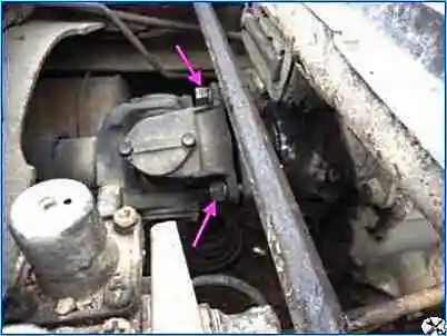
Unscrew the four nuts securing the cardan drive and disconnect the cardan.
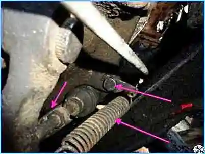
Disconnect the PSU
Unscrew the starter mount
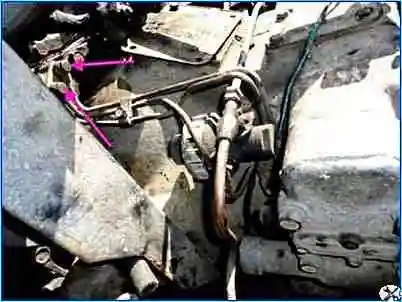
Disconnect the tubes to the reduction gear
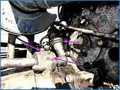
Disconnect the gear shift lever
We install a jack between the engine pan and the flywheel and jack up the power unit through a wooden stand.
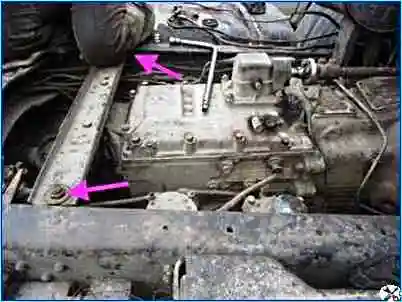
Unscrew the nuts securing the rear yoke and remove it.
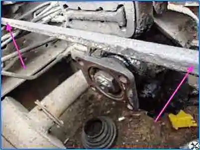
Unscrew the spacer rod
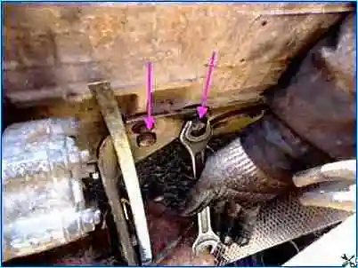
Unscrew the bolts securing the exhaust system bracket.
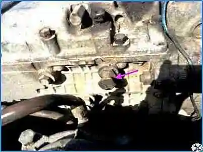
We connect the hoist to special eye bolts and tighten the hoist.
Unscrew the nuts securing the side cushions of the power unit.
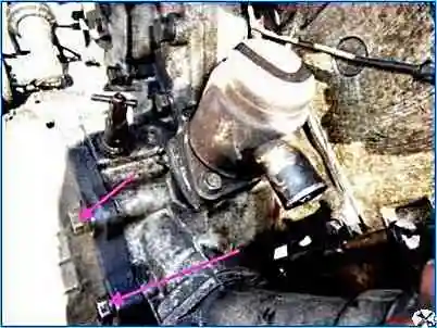
Unscrew the bolts securing the gearbox to the engine.
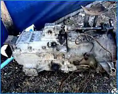
Raising the hoist, we move the gearbox away from the engine to the output of the gearbox input shaft, and remove the gearbox. Install the gearbox in reverse order


