Secure the regulator in a vice with soft jaws by the boss of terminal 1 of housing 5.
Do not secure the regulator by the upper or lower part of housing 5, as this may result in its deformation or destruction.
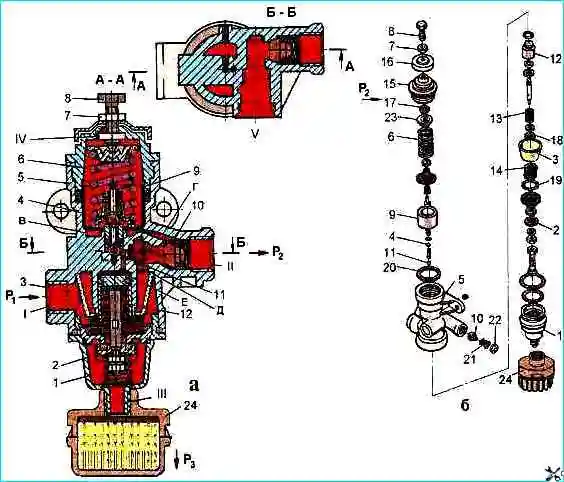
Unscrew lock nut 7 and unscrew adjusting screw 8, loosening spring 6 of the balancing piston.
Then unscrew with a special 50 mm socket wrench mod. and 806.04.006 upper cover 15 and remove spring 6 and balancing piston 9 together with inlet 11 and outlet 4 valves, remove sealing cuff 20.
Unscrew lower cover 1 with noise muffler.
To remove noise muffler it is necessary to unscrew it from the lower cover and remove filter 3 with spring and unloading piston 12 in assembly.
To disassemble unloading piston 12 it is necessary to remove two thrust rings 18 and 19 with round-nose pliers.
To disassemble check valve 10 it is necessary to unscrew washer 22 with round-nose pliers and remove check valve with spring 21.
After disassembling the regulator parts, wash with clean gasoline or acetone, dry and thoroughly inspect.
There should be no cracks, hairlines or other visible defects on the surface of the body parts. The parts should be cleaned of rust and burnt-on deposits.
All rubber parts should be replaced with new ones.
The procedure for assembling the regulator is the reverse of disassembling. The threads on the lower 1 and upper 15 covers must be lubricated with graphite grease during assembly.
Adjusting and checking the pressure regulator after assembly
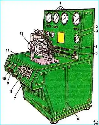
Install the pressure regulator on the test stand (see Fig. 2) and connect the device according to the diagram shown in Fig. 1), a.
Then supply and release air three times under a pressure of 1.4 MPa into terminal I. In this case, terminal V must be plugged
If the limits of the regulated air pressure in terminal II do not correspond to 0.65-0.8 MPa, using the adjusting bolt 8, you should adjust the pressure to the desired limits.
In this case, you should strive to achieve the upper pressure limits, since due to the shrinkage of the springs during operation, a decrease in the set pressure is possible.
After adjustment, check the regulator on and off pressure three times, and then lock the adjusting bolt.
By installing adjusting washers of different thicknesses under the spring of the unloading valve, it is necessary to adjust the actuation pressure of the unloading valve 2. To do this, you need to block the air passage to terminals I and II with a plug.
Increase the pressure in terminal I three times and when the pressure reaches 1.0-135 MPa, the safety valve should open and air should escape through terminal III of the regulator.
After adjustment, release the passage to terminal II
To check the regulator for leaks, you need to set the pressure in terminals I and II 0.05 MPa, while the tightness of the inlet valve II, piston cuff 9 and unloading valve 2 are checked.
The tightness of the check valve 10 is checked by setting the pressure in outlet II to 0.45 MPa.
When soaping, the appearance of air bubbles is not allowed for 1 min.
")

")
")
")
")
")
")
")