The fuel injection advance clutch is used to ensure economical engine operation at various speeds
As the crankshaft rotation speed increases, it automatically increases the advance angle and thereby provides sufficient time for fuel combustion, and when the rotation speed decreases, it reduces this angle.
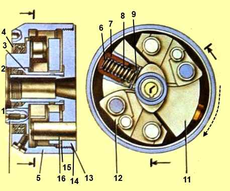
The coupling consists of two coupling halves: driving 1 (Fig. 1) and driven 13.
The driven coupling half 13 is fixed on the conical surface of the front end of the camshaft of the fuel pump with a key and a nut with a washer, the driving pulley coupling 1 is mounted on the hub of the driven coupling half (can be rotated on it).
A housing 5 is screwed onto the driven coupling half, combining the coupling parts.
Weights 11 are loosely placed on fingers pressed into the driven coupling half.
Springs 8 hold the loads against the stop in the sleeve 3. With this sleeve, the driving half of the coupling is freely put on the cylindrical protrusion of the driven half of the coupling.

Spacers 12, mounted on axles integral with the coupling half, are located between the weight pins and their curved surfaces "B".
The torque from the injection pump drive is transmitted to the driving coupling half 1, which, through spacers 12, weights 11 and weight axles 16, rotates the driven coupling half 13, mounted on the toe of the injection pump cam shaft.
At a low speed of rotation of the crankshaft, the weights under the action of springs 8 are in a state brought to the stop against the sleeve 3, and the driven coupling half occupies a certain position relative to the driving half.
As soon as the crankshaft rotation speed begins to exceed 1200 rpm, the resulting centrifugal forces of the loads 11 exceed the forces of the pre-compressed springs 8. As a result, the weights begin to diverge, turning on the axes 16.
Spacers 12 rotate around their axis under the action of the fingers moving apart together with the loads.
Resting the profile surface against the curved surface and sliding along it towards the center, the spacers push the loads in the direction of rotation.
The driven coupling half, together with the pump shaft, rotates as the coupling rotates, increasing the fuel injection advance angle.
At the rated speed, the weights diverge all the way, providing the largest rotation angle of the coupling halves, equal to 4°30', which corresponds to an increase in the installation angle (with the engine not running) of fuel injection advance by 9° of crankshaft rotation.
When the shaft rotation speed decreases, the weights move closer together under the action of springs 8, reducing the advance angle.
To lubricate the rubbing surfaces of the coupling, 0.16 liters of engine oil is poured into it through the holes in the housing, closed with plugs.
Under the influence of centrifugal forces, oil flows to all rubbing surfaces of the parts, and the most loaded interfaces (spacer - surface B of the load, load - axle, spacer - axle) are in the oil bath.
")

")
")
")
")
")
")
")