The clearance in the valve mechanism must ensure a tight fit of the valve to the seat when the rod elongates due to heating and in the event of the head settling in the seat due to wear of the chamfers
The clearance adjustment is carried out on a cold engine no earlier than 30 minutes after stopping it, while the fuel supply is turned off and the car is braked with the parking brake.

The clearances are simultaneously adjusted on two heads in pairs in the order of operation of the engine cylinders.
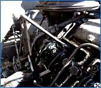
First, the crankshaft is turned until the notch on the flywheel matches.
First, the engine crankshaft is turned and placed in a position characterized by its rotation along the direction of rotation by 60° relative to the start of fuel injection in the first cylinder.
In this position, the valves of the adjustable cylinders (1 and 5) are closed (the rods rotate freely).
To regulate the valves following the order of operation of the cylinders, rotate the crankshaft 180° each time in the direction of rotation.
The operating order of the cylinders is 1—5—4—2—6—3—7—8.
If you twist the flywheel from below by the holes in the flywheel, then first twist from TDC towards the location of the batteries by two holes in the flywheel.
Turn the flywheel clockwise when viewed from the front of the engine (counterclockwise when viewed from behind the engine). And we adjust the gaps in cylinders 1 and 5.
Then through 6 holes in the flywheel the next two cylinders 4 and 2, etc.
Since there are 12 equally spaced holes on the flywheel for scrolling, 6 holes exactly correspond to 180° rotation of the crankshaft.

Before checking the gap, tighten the rocker arm mount nuts and head bolts; at the same time, in order to eliminate possible deformation of the rods, it is recommended to increase the gap by unscrewing the adjusting screws from the rocker arms.

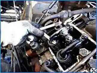
We set the required gap with a feeler gauge 0.30 mm thick for the intake valve and 0.40 mm for the exhaust valve.
Holding the locknut, turn the screw with a screwdriver so that the feeler gauge moves in the gap with noticeable force.
After this, holding the screw with a screwdriver, tighten the locknut, check the gap again with a feeler gauge and, without removing it and turning the rod, make sure that it rotates freely.


