Axial-type fan, five-bladed, creates additional air flow through the core of the radiator of the cooling system
It is mounted on the hub 15 of the driven shaft of the fluid coupling and placed in a casing
When the fan rotates, the shroud creates an air flow directed through the radiator core, thereby increasing cooling efficiency.
The fan drive is hydraulic; it consists of a fluid coupling and a switch for its operation mode.
Fluid coupling of the fan drive ensures the transmission of torque from the engine crankshaft to the fan and reduces dynamic loads that occur when the crankshaft speed changes sharply.
The switch automatically turns the fan on or off.
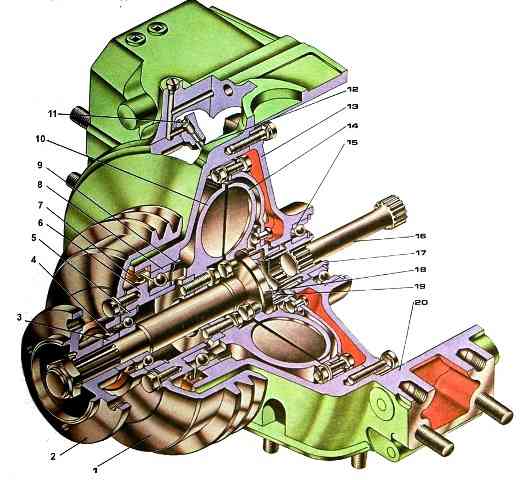
The fluid coupling is installed in the front part of the engine coaxially with the crankshaft in the cavity formed by the front block cover and the bearing housing.
The drive shaft assembly with casing, drive wheel, pulley shaft and generator pulley, connected by bolts and rotating in ball bearings, constitute the driving part of the fluid coupling.
It is driven by the engine crankshaft via a splined shaft.
The driven wheel, assembled with the shaft and the fan hub mounted on it, rotating in ball bearings, constitutes the driven part of the fluid coupling.
The fluid coupling is sealed with rubber cuffs. On the inner toroidal surfaces of the drive and driven wheels there are radial blades cast together with the wheels.
There are 33 of them on the drive wheel, 32 on the driven wheel.
The inter-blade space of the wheels forms the working cavity of the fluid coupling.
Transmission of torque from the drive wheel of the fluid coupling to the driven wheel occurs when the working cavity is filled with oil.
When the engine is running, the oil coming from the pressure section of the oil pump through the switch channel enters the blades of the rotating drive wheel and is carried away by it, acquiring kinetic energy.
Internal oil circulation is established in the wheel cavity (shown by arrows).
Oil particles hitting the blades of the driven wheel give off energy to it, ensuring rotation of the driven parts and the fan.
The rotation speed of the driven wheel depends on the amount of oil entering the fluid coupling cavity.
A sharp change in the engine crankshaft speed is accompanied by slipping of the drive wheel of the fluid coupling relative to the driven wheel, which reduces dynamic loads in the drive.
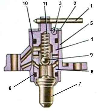
The switch (Fig. 2.), which controls the operation of the fan drive fluid coupling, is installed in the front part of the engine on the pipe so that its thermal power sensor 7 is located in the fluid flow supplied from the pump to the right row of cylinders.
The switch has three fixed positions that determine the fan operating mode.
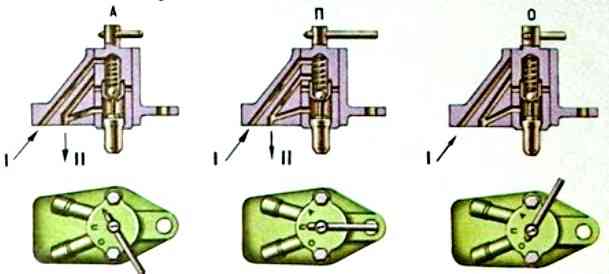
Automatic mode - the lever is set to position A.
If the temperature of the coolant washing the thermal power sensor increases, the active mass located in its cylinder begins to melt and, increasing in volume, moves the sensor rod and ball 9.
At a liquid temperature of 85-90°C, ball 9 opens the oil channel in housing 5.
Oil from the main line of the engine through the channels in the switch body, the block and its front cover, the tube and the channels in the drive shaft enters the operating th cavity of the fluid coupling; in this case, the torque from the crankshaft is transmitted to the fan impeller.
When the coolant temperature is below 85°C, the ball, under the action of a return spring, closes the oil channel in the housing and the oil supply to the fluid coupling stops. In this case, the oil in the fluid coupling is drained through a hole in the casing into the engine crankcase and the fan is turned off.
The fan is turned off - the lever is set to position O (Fig. 3), Oil is not supplied to the fluid coupling.
The impeller can rotate at a low frequency under the influence of friction forces arising during rotation in the bearings and fluid coupling seals.
The fan is constantly on - the lever is set to position P.
Oil is constantly supplied to the fluid coupling, regardless of the coolant temperature, the fan rotates constantly at a frequency approximately equal to the crankshaft speed.
The main operating mode of the fluid coupling is automatic.
If the fluid coupling switch fails in automatic mode (characterized by engine overheating), it should be switched to permanent mode (set the switch lever to position A) and the switch malfunction should be repaired as soon as possible
")

")
")
")
")
")
")
")