The mechanical all-mode direct-acting speed controller with an overdrive gear for the load drive is designed to maintain the engine speed mode set by the driver by automatically changing the amount of fuel supplied depending on the load change
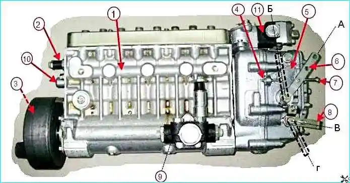
Model 173 high-pressure fuel pump: 1 - fuel pump housing, 2 - bypass valve, 3 - damper clutch, 4 - maximum speed limiting bolt, 5 - speed controller, 6 - controller control lever, 7 - limiting bolt minimum speed, 8 - stop bracket, 9 - fuel priming pump, 10 - starting supply adjustment bolt, 11 - boost fuel supply corrector, (A) - lever position at minimum idle speed, (B) - lever position at maximum idle speed, (C) - bracket position during operation, (D) - bracket position with the supply turned off.
In addition, the regulator limits the maximum engine speed and ensures engine operation in idle mode.
The regulator has a device for turning off the fuel supply at any time, regardless of the engine operating mode.
By automatically maintaining the speed mode under changing loads, the regulator ensures economical engine operation.
The design of the speed regulator is shown in Fig. 2.
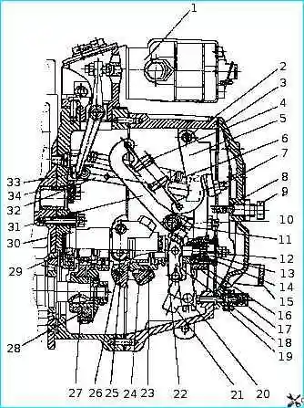
Speed governor: 1 - boost fuel supply corrector; 2 - double-arm lever axis; 3 - inspection hatch cover; 4 - governor spring; 5 - double-arm lever; 6 - rack lever spring; 7 - double-arm lever screw; 8 - buffer spring; 9 - buffer spring housing; 10 - adjusting bolt; 11 - spring lever shaft; 12 - negative corrector; 13 - corrector spring housing; 14 - negative corrector spring; 15 - linkage bracket: 16 - negative corrector bushing; 17 - governor lever; 18 - negative corrector lever; 19 - power adjustment screw; 20 - rack lever; 21 - linkage; 22 - heel; 23 - weight coupling; 24 - governor weights; 25 - weight holder; 26 - weight axis: 27 - pinion gear; 28 - crackers; 29 - weight holder shaft; 30 - cup, 31 - spring lever: 32 - rack rod; 33 - rack; 34 - stop
The regulator is located on the rear end of the high-pressure fuel pump.
On the cone of the camshaft is the drive gear 27 with a damping device.
Rotation from the pump shaft to the drive gear is transmitted through rubber crackers 28.
The driven gear is made as a single piece with the shaft 29 of the weight holder and is mounted on two bearings in the cup 30.
The weight holder 25 (Fig. 2) is pressed onto the shaft, on the axes 26 of which the weights 24 are located.
The weights rest with their rollers against the end of the coupling 23, which through the thrust bearing and the heel 22 transmits the force of the weights to the regulator lever 17, suspended together with the double-arm lever 5 on the common axis 2.
The coupling 23 with the thrust heel 22 in assembly rests on the guide surface of the holder with one end, and is suspended by the other end on the lever 18 of the negative corrector, fixed on the sleeve 16 of the negative corrector.
The heel of the weight coupling is connected through the negative corrector unit to the rack lever 20 and through the rod 32 to the fuel pump rack.
The spring 6 of the rack lever is attached to the upper part of the rack lever, holding the pump rack in a position corresponding to the maximum feed, which ensures an increased fuel supply when starting the engine.
A pin is pressed into the lower part of the rack lever, which enters the hole in the slider of the linkage 21.
The shaft 11 of the regulator lever is rigidly connected to the lever control 6 (Fig. 1) and spring lever 31 (Fig. 2). The movement of the regulator control lever is limited by two bolts 4 and 7 (Fig. 1).
The regulator spring 4 is hooked to the spring lever 31 (short hook) (Fig. 2) and the double-arm lever 5 (long hook), the force of which is transmitted from the double-arm lever to the regulator lever through the screw 7 of the double-arm lever.
An adjusting bolt 10 is screwed into the regulator lever, which rests against the spring lever shaft and serves to adjust the nominal fuel supply.
At the bottom of the regulator lever there is a correcting device (12, 13, 14, 16, 18) with a negative corrector, designed to form the external speed characteristic of the high-pressure fuel pump and engine torque.
The regulator lever is equipped with a side plate holding the sleeve 16 of the reverse corrector and the thrust heel 22 from turning.
In addition, the tail of the side plate mounting bolt, entering the lateral longitudinal groove of the bushing, prevents it from falling out of the lever bore.
Stop 34, fixed to the regulator body, prevents the spring lever 31 from coming dangerously close to the rotating weights.
A stop mechanism consisting of a linkage 21, a bracket 15 and a return spring serves to completely shut off the fuel supply. During operation, the linkage is pressed by the force of the return spring to the adjusting screw.
The back cover of the regulator is closed by the cover 3 of the inspection hatch with a buffer device consisting of a housing 9 and a spring 8, which, smoothing out the vibrations of the lever 17 of the regulator, ensures stable operation of the engine at idle.
The operating principle of the speed regulator is based on the interaction of the centrifugal forces of the weights and the forces of springs with different preliminary deformations.
When the engine is not running, the weights of the regulator are in the reduced position, and the rack 33, under the action of the spring 6 of the rack lever, is in the maximum feed position (the leftmost position).
When the engine is started, when the crankshaft speed reaches 460-500 min -1 (the control lever rests against the minimum speed limit bolt), the governor weights, under the action of centrifugal force, overcome the resistance of the rack lever spring and shift the rack lever 32 through the weight coupling 23 until the negative corrector bushing 16 stops in the governor lever.
Then, overcoming the resistance of the buffer spring 8, the weights move the entire lever system and the high-pressure fuel pump rack to the right until the cyclic feed of the high-pressure fuel pump section is established, corresponding to the minimum speed mode (minimum idle speed mode).
When the control pedal is pressed, the governor control lever and the spring lever 31 rigidly connected to it rotate at a certain angle, which leads to an increase in the tension of the governor spring.
Under the action of the spring, the governor lever 17 moves the lever system, the weight coupling and the rack in the direction of increasing the feed, and the engine crankshaft speed increases.
This occurs until the centrifugal force of the weights balances the tension force of spring 4, i.e. to a stable engine operating mode.
Thus, each position of the governor control lever corresponds to a certain number of engine revolutions.
When the total moment of resistance to the vehicle's movement decreases, the engine crankshaft speed increases. In this case, the centrifugal force of the weights increases.
The weights diverge and, overcoming the force of the governor spring, move the weight coupling 23 and the heel 22.
In this case, the lever system and the rack move in the direction of decreasing feed (to the right) until the engine speed specified by the position of the control lever is established, i.e. until equilibrium is reached between the centrifugal force of the weights and the force of the governor spring.
As the total moment of resistance to vehicle movement increases, the crankshaft speed decreases, and therefore the centrifugal force of the governor weights also decreases.
By the force of the governor spring 4, the lever system, the heel and the weight clutch will move to the left and move the rack to the left, towards increasing the supply.
The fuel supply in sections increases until the engine crankshaft speed reaches the value specified by the position of the governor control lever.
The engine is stopped by turning the linkage bracket 15 downwards.
In this case, the linkage 21 and the lower end of the rack lever 20 turn to the left, the pump rack extends to the extreme position, and the fuel supply stops.
Negative corrector (12, 13, 14, 16, 18) ensures a gradual decrease in the cyclic fuel supply when the rotational speed of the camshaft of the pump decreases to 500 min -1 and thereby ensures smokeless operation of the engine.
At the crankshaft rotational speed corresponding to the nominal one, the centrifugal force of the weights exceeds the pre-tightening force of the corrector spring 14, and the heel rests against the main lever of the regulator through the corrector 12 and the sleeve 16.
When the rotational speed of the camshaft of the fuel injection pump decreases, the force of the corrector spring becomes sufficient to overcome the force of the weights.
In this case, the corrector 12 extends from the sleeve 16 and, moving the weight coupling and the lever system, shifts the fuel injection pump rack towards decreasing the cyclic fuel supply.
The rotational speed of the camshaft corresponding to the moment the corrector starts working, i.e. i.e. the moment the corrector starts to extend from the bushing, it is regulated by preliminary compression of spring 14.
The lower the rotation speed, the greater the amount of the corrector protruding from the bushing and the greater the amount of the fuel cycle supply limitation.
At 500 min -1 the amount of the fuel cycle supply limitation is the greatest, its value is determined by the maximum amount of the corrector protruding.
Regulator The rotation speed is equipped with a boost fuel supply corrector 1 to reduce the heat stress and smoke of the diesel exhaust gases at low rotation speeds and transient modes.
In addition, the corrector protects the engine in emergency situations that occur when the turbocharging system fails.
The principle of operation of the boost corrector is that when the boost air pressure decreases, it affects the fuel pump rail, reducing the fuel supply.
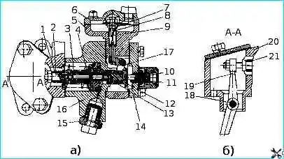
Boost fuel supply corrector: a) horizontal section; b) vertical section: 1 - stop sleeve; 2 - stop; 3 - sleeve spring; 4 - piston spring; 5 - diaphragm housing; 6 - diaphragm cover; 7 - diaphragm rod lock nut; 8 - spring; 9 - rod with diaphragm; 10 - corrector spring housing; 11 - corrector spring; 12 - valve; 13 - piston; 14 - corrector cover; 15 - oil supply nipple; 16 - corrector housing; 17 - lever; 18 - lever axis; 19 - lever; 20 - spacer; 21 - lever adjusting bolt
The boost fuel supply corrector (Fig. 3) is mounted on the upper part of the regulator body.
The corrector body 16, the membrane body 5 and the corrector cover 14 are attached to the spacer 20 using bolts.
A pair of piston 13 and spool 12 is located inside the corrector body. Through the stop 2, the piston is pressed by spring 4 to the corrector body.
A stop sleeve 1 is installed on the stop, which is constantly pressed by spring 3 to the adjusting bolt 21 of lever 19. The lever is mounted on axis 18 in the spacer.
At one end of the lever there is an adjusting bolt with a nut, and the other end directly affects the rack when the corrector is operating Fuel injection pump.
The membrane housing contains a membrane made of special fabric, assembled with rod 9, closed by cover 6.
The cover has a hole for supplying air from the engine intake manifold.
Lever 17, mounted on the axis, serves to transmit movement from the rod to spool 12. The corrector spring 11 rests against the spool.
To change its preliminary compression, the spring housing 10 is screwed into cover 14 of the corrector.
A lock nut and cap are screwed onto the housing. A nipple 15 for supplying oil from the engine lubrication system is screwed into the corrector housing.
The mating parts of the boost corrector are sealed using paronite gaskets.
When the engine is not running, there is no oil pressure in the lubrication system and no air in the intake correctors. Spring 4 presses piston 13 with stop 2 against corrector body 16.
Corrector spring 11 presses spool 12 and rod 9 with membrane until it stops against the membrane cover.
When the engine is started, oil from the engine lubrication system begins to flow through insert 15 into the piston cavity of the corrector and through the open drain windows of the piston, axial channels of the spool, piston and stop it drains into the cavity of the regulator.
When the engine enters idle mode, the fuel injection pump rack moves from the starting position towards decreasing feed.
Following the rack, under the action of spring 3, sleeve 1 moves, turning lever 19.
The movement of the sleeve relative to the stop leads to the overlap of the drain windows of the stop, as a result of which free drainage stops, the oil pressure in sub-piston cavity increases, and the piston begins to move to the left to its working position.
The piston continues to move until the piston drain windows are opened by the end working edge of the spool.
When the engine is running under load and the crankshaft speed increases, the air pressure in the membrane cavity increases.
The membrane is deformed, the rod moves the corrector lever 17, which in turn shifts the corrector spool to the right.
In this case, the cross-sectional area through which oil flows from the sub-piston cavity to the axial channel of the piston increases, the oil pressure in the sub-piston cavity decreases, and the piston together with the stop, under the action of the spring, shifts to the right, restoring its position relative to the spool.
Following the piston and the stop, under the action of the starting spring, the fuel injection pump rack moves.
Thus, the increase in air pressure in the membrane cavity leads to an increase in the cyclic fuel supply.
The rack movement is accompanied by the rotation of the lever 19, while the amount of rack movement and change in cyclic supply is determined by the amount of piston and stop movement.
When the crankshaft speed decreases, the turbocharger pressure drops, the pressure in the membrane cavity decreases, the spool valve 12, under the action of the spring 11, shifts to the left and the working edge of the end surface of the spool valve covers the piston drain windows.
The oil pressure in the sub-piston cavity increases, the piston shifts to the left until the drain windows open and through stop 2 and lever 19 shifts the rack towards decreasing the feed.
Thus, a change in air pressure in the membrane cavity leads to a change in the position of the spool, the piston automatically tracks the position of the spool and ensures the corresponding movement of the fuel injection pump rack.
The amount of rack movement and the change in cyclic feed are determined by the magnitude of the pressure drop in the membrane cavity and the characteristic of the corrector spring.
When the boost pressure increases by about 0.06 MPa (0.6 kgf/cm 2), the corrector removes the feed limitation.
When the engine is stopped, the corrector ensures automatic activation of the starting feed.
Dismantling the boost corrector together with spacer 20 during operation is not recommended, since then incorrect installation of lever 19 relative to the rack is possible, leading to wear engine.
If it is necessary to dismantle it (for example, during repairs), when subsequently installing the corrector on the regulator, use the engine linkage bracket to move the pump rack to the off supply position and insert the corrector with a spacer into the regulator body.
Then release the linkage bracket.
After this, it is necessary to check the corrector adjustment for boost, as well as check the regulator for turning off the fuel supply.
Main adjustments provided by the regulator design
The minimum idle speed is adjusted by bolt 7 (Fig. 1) and the buffer spring body 9 (Fig. 2);
The maximum idle speed (start of rack ejection) is adjusted by bolt 4 (Fig. 1).
The nominal power (feed) is adjusted by bolt 10, adjusted by screw 19 (Fig. 2).
The preliminary spring tension (the difference in revolutions of the end and start of rack ejection) is adjusted by screw 7 (Fig. 2).
The fuel supply at 500 min-1 is adjusted by the nut of the reverse corrector 12 (Fig. 2);
The preliminary tension of the spring of the reverse corrector (the revolutions of the start of the corrector operation) is adjusted by the corrector housing 13 (Fig. 2).
The features of the adjustment should include the fact that in order to ensure reduced force on the control lever, the spring lever when adjusting the speed of the start of the regulator action should be as close as possible to the stop in the housing regulator, limiting its rotation.
Adjust the regulator's start of action with the screw of the double-arm lever
")

")
")
")
")
")
")
")