To remove the generator, disconnect the battery mass, raise the cab of the KamAZ vehicle and disconnect the terminals “+”, “—”, B
Loosen the pinch bolt of the split support of the generator bracket, then unscrew the nut of the stud securing the generator to the bracket, unscrew the bolt securing the generator to the tension bar and remove the generator.
To install the generator on the bracket, insert the generator pin into the split support, and the bracket pin into the hole in the front cover of the generator, put on the spring washer and screw the nut onto the pin by hand.
Install the drive belts on the generator pulley, ensuring that the axes of the generator pulley and the engine pulley coincide within ±1 mm.
Ensure that the axes coincide by moving the generator.
Place the spring washer onto the bolt securing the generator to the tension bar, align the holes in the bar and the generator cover and screw in the bolt, setting the required tension of the drive belts by moving the generator.
Tighten the bolt securing the generator to the bar, tighten the nut securing the generator to the bracket stud and tighten the pinch bolt of the split generator support.
To avoid damage to the generator brackets, follow the stated procedure for tightening fasteners.
Connect terminals “—”, “+” and “B”.
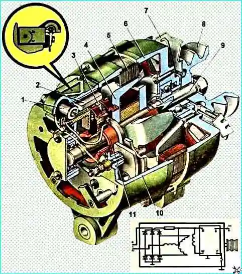
When repairing a generator, it is recommended to eliminate malfunctions by replacing damaged parts and assembly units, and for this it is not always necessary to completely disassemble the generator. Repair of individual parts is allowed.
To disassemble the generator:
- - unscrew the bolts securing the brush holder to the cover and remove the brush holder assembly with the voltage regulator;
- - unscrew the screws securing the ball bearing cover;
- - unscrew the tightening screws securing the generator cover;
- - remove the cover from the side of the slip rings along with the stator;
- - disconnect the phase terminals of the stator winding from the terminals of the rectifier unit and separate the stator;
- - unscrew the pulley fastening nut, having first secured the rotor to one of the poles or holding it with a wrench, and remove the pulley;
- - remove the fan, remove the segment key from the groove and remove the thrust bushing;
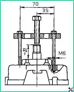
- - remove the cover on the drive side together with the ball bearing from the rotor shaft using a special puller (Fig. 2), using the threaded holes in the cover for this purpose;
- - remove the ball bearing from the shaft;
- - remove the rectifier block from the cover on the slip ring side.
After disassembly, clean all metal parts and assembly units of the generator from dirt, except for bearings and assembly units containing windings, insulating parts and semiconductor devices, degrease, wash with gasoline and dry, and wipe the rest with a rag soaked in gasoline.
Inspect and replace parts with mechanical damage.
Cracks passing through the hole, hole wear of more than 17.02 mm and chips of the pulley edges of more than 2 mm are not allowed on the pulley.
Check the wear of the belt pulley groove.
The pulley is allowed for installation if, when installing control rollers with a diameter of 14 mm into the groove, the diameter measured along the rollers is at least 83.5 mm.
Fix bent fan blades by straightening and straightening.
If the hole in the cover mounting bracket on the slip ring side and the drive side cover is worn or out of shape by more than 10.3 mm, drill a hole.
Worn bearing hole in the cover on the slip ring side to a diameter of more than 35.02 mm, and in the cover on the drive side - more than 47.05 mm, process to a size of 38.0-38.05 mm and 50.00- 50.05 mm, respectively, and then press in the repair ring while maintaining the same seating size for the bearing.
When assembling the generator, to ensure alignment of the generator mounting holes on the engine, insert a tightly fitting rod into them before assembly. After securing the tie bolts, remove the rod.
After assembly, check by hand the ease of rotation of the shaft and the technical condition of the generator.
Checking the rotor field winding
Check the serviceability of the winding with a tester (ohmmeter), while keeping an eye on the reliable contact of the tips of the instrument's measuring leads with the slip rings of the rotor.
The resistance value must correspond to the value specified in the technical specifications of the generator, if the winding does not have short-circuited turns.
If there is a break in the winding, the ohmmeter needle does not deviate.
The serviceability of the winding and the reliability of the contact of the brushes to the slip rings can be checked on the stand without disassembling the generator.
When the voltage of the DC power source is 28 V connected to the winding plugs, the amount of current consumed should not exceed the value specified in the technical specifications of the generator.
If there is a break in the winding, the ammeter needle will not deviate.
Determine whether the field winding is shorted to ground using a test lamp or a voltmeter at a voltage of 220-250 V.
If there is no current within 1 minute, then the winding insulation is good.
If a break is detected in the excitation winding, inspect the places where the ends of the winding are soldered to the slip rings and, in case of unsoldering, restore the broken connection.
If there is a break inside the winding or an interturn short circuit or a winding short to ground is detected, replace the rotor.
Check the stator winding separately, after disassembling the generator, with the winding leads disconnected from the rectifier block.
To determine a break in the stator phase winding, alternately connect two phases of the winding to a tester (ohmmeter) or through a test lamp to a current source with a voltage of 12-30 V.
In the event of a break in any of the windings when connecting it to the terminals of the other two, the tester (ohmmeter) needle does not deviate and the control lamp does not light up.
If the phase winding is in good condition, the ohmmeter readings should correspond to the values specified in the technical specifications.
Check the turn-to-turn short circuit of the stator winding with a portable flaw detector model PDO-1.
Check the short circuit of the stator winding to ground due to mechanical or thermal damage to the insulation of the winding or terminals with a test lamp under a voltage of 220-250 V by connecting one conductor to the stator core, and the other to one of the winding terminals.
If the lamp does not light up, there is no short circuit.
Check the condition of the insulation of the winding wires; the insulation should not show signs of overheating.
If the phase lead from the tip breaks, unwind one or two turns of the winding, install an insulating pipe and compress or solder the tip.
Checking the technical condition of the generator
The cause of failures in the operation of the generator set may be a malfunction of the generator, voltage regulator, or electrical contact failure in the power supply system circuit.
Therefore, before starting the test, make sure that the electrical contact of the wires is reliable at the terminals of the generator, the voltage regulator, in the connecting blocks between the wire bundles and that the relay for disconnecting the generator excitation winding is in good condition.
Check the presence of current in the excitation circuit using a test lamp.
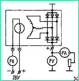
Check the technical condition on a stand that allows you to change the generator rotor speed, current load and measure voltage, current and generator rotor speed.
Power the excitation winding from a direct current source. Supply voltage 28 V.
Select measuring instruments so that the measured values are within 30-95% of the scale.
The device for measuring current must have an accuracy class of at least 1.5, and voltage - 1.0.
")

")
")
")
")
")
")
")