Design and operation of Kamaz trailer brake drive devices
The brake drive of a trailer (semi-trailer) of a tractor vehicle is combined (single-wire and two-wire),
includes trailer brake control valve 6 with a two-wire drive, a single safety valve 2, trailer brake control valve 9 with a single-wire drive, three disconnect valves 3 and three connecting heads - two heads 4 of the Palm type for a two-wire trailer brake drive and one head 10 type A for a single-line drive of trailer brakes, pipelines and hoses connecting the devices.
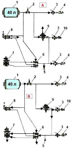
The trailer brake drive is powered from receivers 1 of the parking and spare brake drive circuit.
The trailer brake control valve with a two-wire drive operates in the presence of two autonomous connecting lines - supply and control
It consists of three sections:
- - lower (terminal “I”) operates when the brake drive circuit of the front axle of the working brake system is operating;
- - upper (terminal “III”) – when the brake drive circuit of the wheels of the rear bogie of the service brake system is operating;
- - middle (pin “II”) – when the brake drive circuit of the parking or spare brake systems is operating
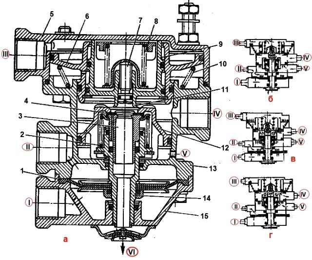
Trailer brake control valve with two-wire drive: a - device; b - initial (inhibited) position; c - position when braking with the service brake system; d - position when braking with a parking or backup system; "I" - output to the lower section of the vehicle's front axle brake control valve; "II" - output to the manual valve for controlling the parking and spare brake systems; "III" - output to the upper section of the brake control valve of the rear truck of the vehicle; "IV" - output to the trailer brake control line; "V" - output to the air cylinder; VI - atmospheric output; 1 - diaphragm; 2, 8, 10 - springs; 3 - unloading hole; 4 - exhaust valve; 5 - upper body; 6 - upper large piston; 7 - adjusting screw; 9 - upper small piston; 11 - exhaust valve; 12 - middle piston; 13 - middle body; 14 - rod; 15 - lower body
In addition, in the middle section there are two more terminals: terminal V is connected to the air cylinder of the parking and spare brake systems; terminal IV - with a control line for a two-wire drive and a trailer brake control valve with a single-wire drive.
The valve controls the trailer brakes - supplies compressed air from the source (terminal "V") to consumers (terminal "IV") - with three independent commands acting simultaneously and separately; in this case, a direct action command is sent to terminals “I”, “III” (to increase the pressure when air is supplied by a two-section brake valve), to terminal “II” - a reverse action command (to reduce pressure when air is released by a manual brake valve)
The main parts of the valve are: upper 5, middle 13 and lower 15 body (sections); large 6 and small 9 upper pistons with their own springs 10 and 8, respectively; middle piston 12 with inlet valve 4, constantly pressed by a spring to the piston seat, and rod 14; exhaust valve 11; unloading hole 3.
In the braked position (Fig. 2 b), compressed air is constantly supplied to terminals “II” and “V”, which, acting from above on diagram 1 and from below on piston 12, holds rod 14 together with piston 12 in the lower position, since the area of the diaphragm is larger than the area of the piston
In the upper part of the body, pistons 6 and 9, under the action of spring 10, are in the uppermost position and the exhaust valve 11 is torn off from the seat made in valve 4, and the inlet valve 4 is closed under the action of spring 2.
In this case, the IV output is through the relief holes 3 of the valve and rod
When braking (Fig. 2, c), compressed air from the brake valve section is supplied to terminals “I” and “II”.
Under the action of compressed air supplied to terminal I, rod 14, together with the middle piston 12 and valve 4, moves upward.
Compressed air supplied to terminal “III” moves the upper pistons 6 and 9 down, compressing spring 10.
In this case, the exhaust valve 11 sits in the valve seat 4, disconnecting the terminal “IV” from the atmospheric terminal “VI”, and then removes the valve 4 from the seat of the middle piston 12
Compressed air from terminal “V” connected to the air cylinder flows to terminal “IV” and then into the trailer brake control line until the force from the air pressure on piston 9 from below is balanced by the force acting on piston 9 from above, developed by the pressure of compressed air and spring 8, and the force from the air pressure on the middle piston 12 will not be balanced by the force from the air pressure acting on the diaphragm 1 from below, i.e., tracking pressure is carried out
When braking (Fig. 2, b), compressed air is removed from terminals I and “III” through an atmospheric hole in the brake valve.
Pistons 6 and 9, under the action of spring 10 and compressed air, occupy the upper position, rod 14 with piston 12 occupy the lower position.
Valve 11 detaches from valve seat 4 and communicates terminal “IV” with atmospheric terminal “VI”
When compressed air is supplied to terminals “I” or “III” separately, the rod 14 with piston 12 moves upward, or the large 6 and small 9 pistons move downward.
Braking and unbraking occurs in the same way as already described
When braking with the spare or parking brake system of a car (Fig. 2, d), compressed air from terminal “II” escapes into the atmosphere through an atmospheric hole in the manual reverse-action brake valve.
The pressure above the diaphragm 1 drops and thereby reduces the force acting on the diaphragm and with it on the rod 14 and the piston 12 from above.
Under the influence of constant pressure of compressed air supplied to terminal “V”, the piston 12 together with the rod 14 moves upward.
In this case, valve seat 4 rests on valve 11, disconnecting terminal “IV” from the atmosphere, and then valve 4 is torn away from piston seat 12 and terminal “IV” communicates with terminal “V”.
Compressed air enters the controlled line of the trailer
The pressure in the trailer brake control line increases until the force acting on piston 12 from below is balanced by the force acting on diaphragm 1 and piston 12 from above, which ensures the follower action of valve 4
When compressed air is supplied to terminal “III” or simultaneously to terminals “III” and I, the pressure in terminal “IV” connected to the trailer brake control line exceeds the air pressure supplied to terminal “III” by 20-100 kPa (0.2-1.0 kgf/cm 2), which ensures the leading action of the trailer (semi-trailer) brakes.
Regulation of the excess pressure is carried out by screw 7 (Fig. 2, a): when screwing in the screw, the excess increases, when turning it out, it decreases.
Diagrams of brake systems for KamAZ vehicle trailers
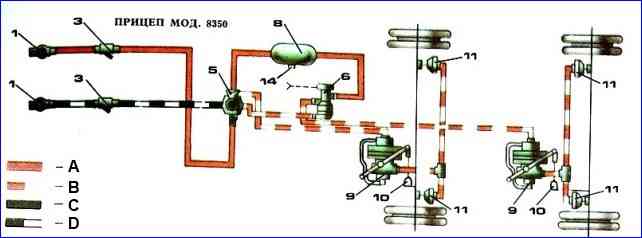
Trailer model 8350: 1 – Palm type connecting head; 2 – connection head type “B”; 3 – main filter; 4 – two-line valve with pressure limitation; 5 – combined air distributor; 6 – solenoid valve; 7 – single safety valve; 8 – receiver; 9 – automatic brake force regulator; 10 – elastic element; 11 – brake chamber; 12 – control valve; 13 – tap for inflating tires; 14 – condensate drain valve; A – supply line; B – control line; C – connecting line; D – control line
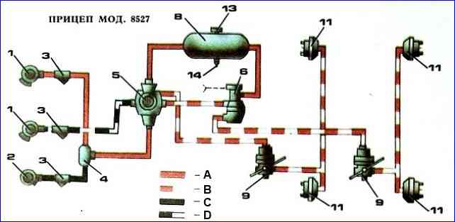
Trailer model 8527: 1 – Palm type connecting head; 2 – connection head type “B”; 3 – main filter; 4 – two-line valve with pressure limitation; 5 – combined air distributor; 6 – solenoid valve; 7 – single safety valve; 8 – receiver; 9 – automatic brake force regulator; 10 – elastic element; 11 – brake chamber; 12 – control valve; 13 – tap for inflating tires; 14 – condensate drain valve; A – supply line; B – control line; C – connecting line; D – control line

Trailer model 8352: 1 – connecting Palm type head; 2 – connection head type “B”; 3 – main filter; 4 – two-line valve with pressure limitation; 5 – combined air distributor; 6 – solenoid valve; 7 – single safety valve; 8 – receiver; 9 – automatic brake force regulator; 10 – elastic element; 11 – brake chamber; 12 – control valve; 13 – tap for inflating tires; 14 – condensate drain valve; A – supply line; B – control line; C – connecting line; D – control line
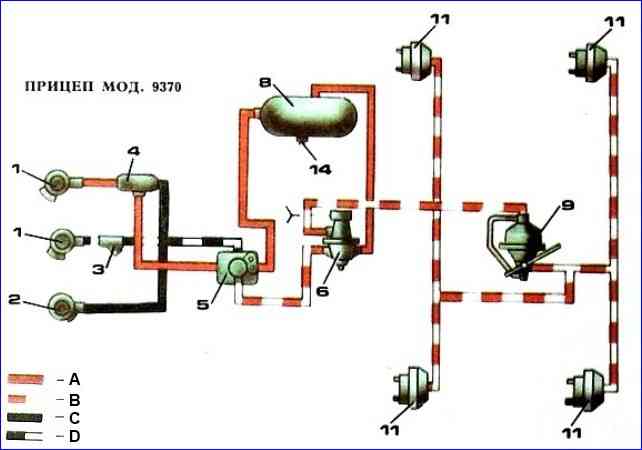
Trailer model 9370: 1 – Palm type connecting head; 2 – connection head type “B”; 3 – main filter; 4 – two-line valve with pressure limitation; 5 – combined air distributor; 6 – solenoid valve; 7 – single safety valve; 8 – receiver; 9 – automatic brake force regulator; 10 – elastic element; 11 – brake chamber; 12 – control valve; 13 – tap for inflating tires; 14 – condensate drain valve; A – supply line; B – control line; C – connecting line; D – control line