Intermediate shaft of KamAZ gearbox
The intermediate shaft 11 has two supports: a cylindrical roller bearing installed in the socket of the front end of the crankcase, and a spherical roller bearing mounted in the cup 34.
The front end of the intermediate shaft is splined and is designed to connect to the divider intermediate shaft (in a ten-speed transmission).
The roller bearing is located on the shaft journal all the way through the thrust washer to the end of the gear 9 and is closed with a cover 10.
The gears of the first gear, reverse gear and second gear are made integral with the shaft, gears 5 of the third gear, 6 of the fourth gear and 9 of the intermediate shaft drive are pressed onto the shaft and additionally secured with segment keys.
All gears are fixed on the shaft by a thrust ring installed in the groove of the shaft between the inner ring of the bearing and the end of the intermediate shaft drive gear.
The first gear and reverse gears are straight-cut, the rest are helical.
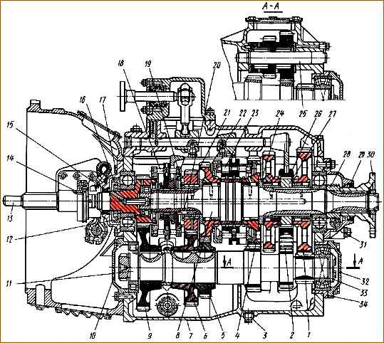
Five-speed gearbox with clutch housing assembly: 1 - first gear gear of the secondary shaft; 2 - reverse gear block; 3 - drain plug; 4 - second gear of the secondary shaft; 5 - third gear of the intermediate shaft; 6 - fourth gear of the intermediate shaft; 7 - crankcase; 8 - secondary shaft; 9 - intermediate shaft drive gear; 10 – cover of the front bearing of the intermediate shaft; 11 - intermediate shaft; 12 - ring nut for fastening the bearing; 13 - input shaft; 14 - clutch release clutch; 15 - cuff; 16 - oil injection ring; 17 - cover of the rear bearing of the input shaft; 18 - synchronizer for fourth and fifth gears; 19 - thrust washer; 20 - lock key of the thrust washer; 21 - fourth gear gear of the secondary shaft; 22 - third gear gear of the secondary shaft; 23 - synchronizer for second and third gears; 24 - reverse gear bushing; 25 – axis of the reverse gear block; 26 - reverse and first gear clutch; 27 - first gear bushing; 28 - speedometer drive worm; 29 - cuff of the secondary shaft bearing cover; 30 - flange; 31 - cover of the rear bearing of the secondary shaft; 32 - rear cover of the intermediate shaft; 33 - thrust washer; 34 - bearing cup
A spherical bearing is installed on the rear wall of the intermediate shaft.
The inner ring of the bearing is pressed all the way into the end of the first gear gear and fixed on the shaft with a thrust washer screwed to the shaft with two bolts.
The outer ring of the bearing is installed in cup 34.
Axial forces arising during operation of the gearbox are absorbed by a spherical roller bearing.
A block of 2 reverse gears is mounted on an axle in two roller bearings.
The axle is fixed in the crankcase with a locking bar. The block has two spur gears.
The larger diameter ring is in constant engagement with the intermediate shaft ring, and the smaller diameter ring is in constant engagement with the secondary shaft reverse gear.
Axial movements of the gear block are limited by two thrust washers. The washers are secured with pins to prevent rotation.
To ensure smooth alignment of the peripheral speeds of the gears and thus the possibility of shock-free engagement of fourth and fifth, second and third gears, inertial synchronizers with conical friction rings are installed.
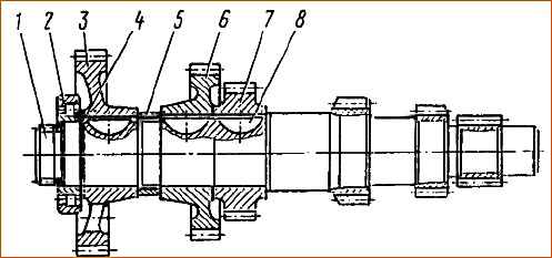
Disassembling the intermediate shaft of the gearbox: 1 – third gear gear wheel; 2 – intermediate shaft; 3 – segmental key; 4 – gear wheel of fourth gear; 5 – spacer sleeve; 6 – gear wheel of the intermediate shaft drive; 7 – thrust ring; 8 – front roller bearing
Removing the front intermediate shaft bearing
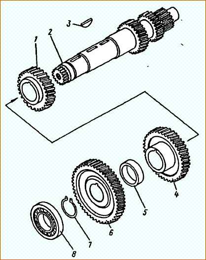
Intermediate shaft assembly: 1 - intermediate shaft; 2 - front roller bearing; 3 – intermediate shaft drive gear; 4 - retaining ring; 5 - spacer sleeve; 6 - 4th gear gear; 7 – third gear gear; 8 - segment key
Technical conditions for installation and repair of the intermediate shaft of the gearbox
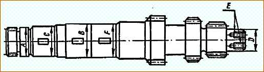
Not allowed:
- - cracks and breaks;
- - chipping of the working surfaces of gear teeth;
- - neck diameter “A” for the front bearing is less than 64.992 mm;
- - neck diameter “D” for the rear bearing is less than 49.983 mm;
- - the width of the keyways is more than 10.02 mm;
- - neck diameter “C” is less than 65.235 mm, “B” is less than 69.835 mm, “F” is less than 70.035 mm
Synchronizer for second and third gears
The synchronizer for the second and third gears consists (Fig. 2) of a carriage 5, two friction rings 2 to 4, eight locking fingers 3 and four locking fingers 1.
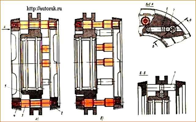
Synchronizer for second and third gears: a - device; b - position when engaging third gear; 1 - locking pin; 2 - second gear friction ring; 3 - blocking finger; 4 - third gear friction ring; 5 - synchronizer carriage; 6 - clamp spring; 7 - ball
There is a groove machined on the carriage into which the nuts for the second and third gear shift forks fit.
The carriage has an internal splined hole, consisting of three toothed rims, with which it is connected to the splined part of the secondary shaft.
The carriage constantly rotates along with the secondary shaft.
The outer ring gears are thinner than the middle one and, in combination with the gear ring of the secondary shaft, when engaging second or third gear, form a “lock” that prevents the gears from switching off automatically while the vehicle is moving.
In the carriage along the circumference, parallel to the axis, there are eight holes for the locking pins and four holes for the locking pins.
The holes for the locking pins are chamfered on both sides with an angle equal to the angle of the chamfers of the locking pins.
In the neutral position, the locking fingers are in the holes of the carriages with a gap. Friction rings are pressed onto the outer ends of the locking pins until they stop at their ends.
Rectangular grooves are made on the conical surface of the rings to remove wear products, and helical grooves are cut around the circumference to squeeze out oil from the conical friction surfaces when the ring is pressed against the cone of the gear wheel being engaged, which increases the friction force between them.
Fingers 1 of the clamps are installed in the holes of the carriage between friction rings 2 and 4. In the middle part of the fingers there is a groove into which ball 7 fits, pressed by spring 6.
In the neutral position, under the action of spring 6, the ball is pressed against the ring, enters its groove and prevents spontaneous movement of the carriage. To move the carriage out of the middle position, force must be applied.
The synchronizer works as follows.
When, for example, third gear is engaged (Fig. 6 b), the synchronizer carriage 5 tends to move to the left under the action of the gear shift fork.
During the initial movement, the carriage moves together with the pins of the clamps and friction rings until the conical surface of the ring touches the cone of the third gear gear.
Since previously the movement was carried out in second gear, and the carriage is rigidly connected to the secondary shaft, the peripheral speed of the carriage is less than the peripheral speed of the third gear gear of the secondary shaft, which is in constant engagement with the third gear gear of the intermediate shaft.
When the cone of the friction ring comes into contact with the cone of the third gear gear, the latter, under the influence of friction forces, drags the carriage along with it, turning it relative to the locking pins 3.
The chamfers of the carriage holes rest against the chamfers of the locking fingers, and its further movement until the peripheral speeds are completely equalized.
The angle of inclination of the chamfers is selected so that while the friction moment is in effect, i.e., while the synchronization of ring 4 and gear 22 occurs (see Fig. 1), further movement of the carriage along the splines of the secondary shaft is impossible.
When the peripheral speeds become equal, the friction moment disappears, the locking fingers 3 (Fig. 6) will take a neutral position relative to the holes in the carriage 5 and it will move in the axial direction under the action of the gear shift fork.
In this case, the balls of the clamps 7 are recessed and the carriage moves along the large diameters of the locking pins 3 towards the third gear.
The toothed end of the carriage silently engages with the ring gear of the third gear.
Engaging second gear occurs similarly to The only difference is that in this case the peripheral speed of the carriage will be greater than the peripheral speed of gear 4 (see Fig. 1) of the second gear and when the cones touch, the carriage will slow down under the influence of the friction moment, turning relative to the locking pins in the opposite way than when engaging the third gear , direction.
The principle of operation of the synchronizer for the fourth and fifth gears is no different from the principle of operation of the synchronizer for the second and third gears, but it is structurally designed somewhat differently.
")

")
")
")
")
")
")
")