The lubrication system ensures the supply of oil to the rubbing surfaces of parts, which reduces friction between them and their wear, and also reduces engine power losses due to overcoming friction forces
During engine operation, the oil introduced between the parts circulates continuously; at the same time, it cools the parts, protects them from corrosion and removes wear products.
A thin layer of oil on the pistons, piston rings and cylinders not only reduces their wear, but also improves engine compression.
The lubrication system of the KamAZ vehicle is combined. This means that oil is supplied to the rubbing parts in several ways: under pressure, splashing and gravity.
Oil under pressure is pumped into the gaps between the most heavily loaded rubbing parts:
- - to the main and connecting rod bearings of the crankshaft, camshaft bearings;
- - to the rocker arm bushings and the upper tips of the pusher rods;
- - to the bearings of the high-pressure fuel pump, brake pneumatic compressor and turbochargers.
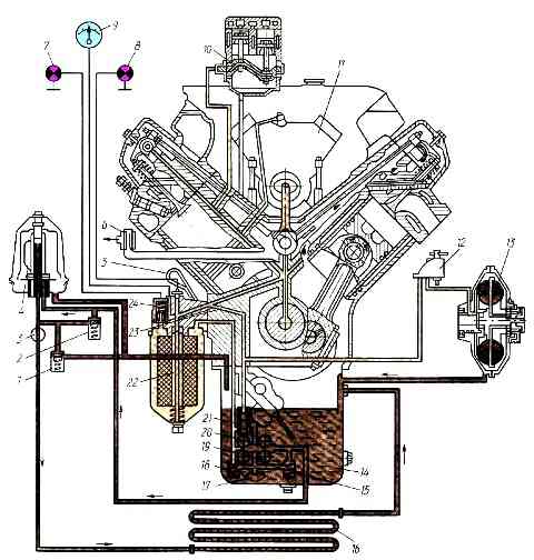
Lubricating system diagram: 1 - oil radiator drain valve; 2 - bypass valve of the centrifugal filter; 3 – oil radiator valve; 4 - centrifugal oil filter (centrifuge); 5 - oil level indicator; 6 - breather; 7 - indicator lamp for full-flow oil filter clogging; 8 - warning lamp for low oil pressure; 9 - pressure gauge; 10 - compressor; 11 - high pressure fuel pump; 12 - fluid coupling switch; 13 - hydraulic coupling of the fan drive; 14 - oil pan; 15, 18 - safety valves of the radiator and pressure sections of the oil pump; 16 - oil cooler; 17 - oil receiver; 19, 20 - radiator and pressure sections of the oil pump; 21 - differential valve of the lubrication system; 22 - full-flow oil filter; 23 - main oil line; 24 - bypass valve of a full-flow filter with a clogging alarm
The lubrication system consists of an oil pump installed on the lower plane of the crankcase inside the pan 14 (Fig. 1), a full-flow oil filter 22, a centrifugal oil filter (centrifuge) 4, an oil line 23 with channels, a radiator 16, an oil filler neck , oil level indicator.
The oil reservoir is the oil pan.
Oil is poured into it through the neck to the level of the top mark on the level indicator (dipstick). The bottom mark shows the minimum allowable amount of oil.
The deep part of the pan of KamAZ vehicles with a 6X4 wheel arrangement is located in the rear part of the engine, on KamAZ-4310, -43105 vehicles - in the front part of the engine. This is due to the layout of the vehicles.
During engine operation, oil from sump 14 is sucked through a mesh oil receiver 17 by a two-section pump.
From here, a smaller part of the oil through the channels of the crankcase and the front cover of the block is constantly pumped by the radiator section into centrifuge 4.
Oil purified by a centrifuge through tap 3 enters radiator 16, where it is cooled and then drained into the pan.
When valve 3 is closed or the oil pressure in the radiator increases to 50-70 kPa, it flows from the centrifuge through the opened drain valve into the pan, bypassing the radiator.
Most of the oil enters the suction cavity of the discharge section of the oil pump and is fed by its gears into the full-flow filter 22, where it is cleaned, passing through two filter elements connected in parallel, and then through a channel in the block enters the main line 23.
From this line, oil is supplied through channels in the partitions and walls of the cylinder block to the main bearings of the crankshaft, camshaft bearings and rocker arm bushings of the gas distribution mechanism.
From the annular grooves on the main bearing shells, through the channels in the main journals and cheeks of the crankshaft, the oil enters the dirt cavities of the connecting rod journals, where it undergoes additional centrifugal cleaning, and then goes to lubricate the connecting rod bearings.
Oil squeezed out of the gaps is sprayed by the rotating parts of the crank mechanism, and an oil mist is formed, which settles on the surface of the cylinder liners, pistons, pushers and other parts and thus lubricates them.
Oil removed from the cylinder walls by the oil scraper ring is discharged into the piston and lubricates the piston pin supports in the bosses and the connecting rod upper head bearing.
Through channels in the short arms of the rocker arms of the gas distribution mechanism and in the adjusting screws, oil is supplied to the upper tips of the rods.
Flowing down the rods, it lubricates their lower tips, pushers, and then enters the pan.
The tips of the rocker arms and valve stems are lubricated with oil, which flows from the gaps of the rocker arm bushings and is sprayed by moving parts, then it is discharged through inclined channels into the cavity for the rods and then into the sump.
Part of the oil from the main line is supplied through a channel in the cylinder block and tube into the cavity of the high-pressure fuel pump, lubricates its bearings and parts of the speed controller, and then through the drain pipe enters the engine crankcase.
Oil is pumped from the main line to both the turbocharger bearings and the crankshaft of the brake pneumatic compressors.
There is also a constant supply of oil under pressure to switch 12 of the fan drive fluid coupling.
When the switch is open, the oil enters the working cavity of the fluid coupling 13, from where it drains into the oil pan.
The oil pressure in the system is controlled by pressure gauge 9 on the instrument panel in the cockpit.
In addition, there is an emergency pressure alarm.
When it becomes less than 70 kPa, the red light 8 on the pressure gauge lights up. In this case, it is necessary to stop the engine and identify the cause of the malfunction.
Lamp 7 serves to signal that the filter elements of oil filter 22 are extremely clogged.
The constant glow of this lamp indicates that the bypass valve has opened and uncleaned oil enters the main line, bypassing the filter elements.
Short-term (until the engine warms up) lighting of the warning lamp 7 is allowed; if it is constantly lit, it is necessary to replace the filter elements.
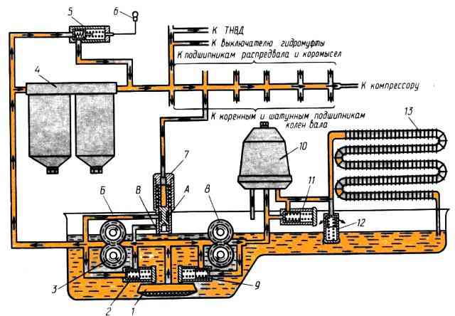
Lubricating system valves: 1 – oil receiver; 2, 9 - safety valves of the discharge and radiator sections; 3, 8 - discharge and radiator sections of the oil pump; 4 - full-flow oil filter; 5 - bypass valve with clogging indicator; 6 - indicator lamp for full-flow oil filter clogging; 7 - differential valve of the lubrication system; 10 - centrifugal oil filter; 11 - centrifuge bypass valve; 12 - centrifuge drain valve; 13 - oil cooler
Lubricating system valves. Oil is supplied to the rubbing parts under a certain pressure.
If it is insufficient, then due to a decrease in the flow rate in the gaps, the washing out of wear products from them and the cooling of parts worsen.
Excessive pressure increases the load on the assembly units of the lubrication system and the energy consumption to drive the oil pump.
Oil pressure in the line depends on the crankshaft speed, oil temperature, degree of wear of parts, resistance of oil filters, radiator, etc.
To ensure that normal operation is not disrupted by changes in these factors, the system is equipped with automatically operating plunger valves.
There are six of them in total: three for the oil pump - safety ones and 2 (Fig. 2) for the radiator and discharge sections, respectively, and valve 7; for a centrifuge - drain valve 12 and bypass valve 11, and one bypass valve 5 for a full-flow oil filter.
Valve 7 is necessary to maintain normal oil pressure (400-550 kPa) in the main line of a warm engine.
According to the principle of operation, the differential valve is a plunger with an annular groove “A”.
On one side it is loaded by the force of oil pressure from the main line, and on the other - by a spring.
In this case, the pressure force transmitted directly from the pressure section of the oil pump through channel “B” to the groove “A” does not upset the equilibrium, since it acts on the end surfaces of the groove of equal area.
When the pressure in the main line exceeds the permissible limit, the valve, overcoming the resistance of the spring, will move and groove “A” will connect channels “B” and “C”, as a result of which the oil from the pump will freely drain through channel “B” into the sump.
Bypass valve 5 comes into operation when the filter elements of full-flow filter 4 are clogged.
On one side, valve 5 is acted upon by the pressure force of the crude oil, and on the other, by the pressure force of the purified oil and the force of the spring, adjusted to the difference (difference) in pressure before and after the filter, equal to 250-300 kPa.
When the filter resistance exceeds the pressure drop value, the valve opens and part of the oil is bypassed into the main line bypassing the filter.
Thus, when the bypass valve is activated, emergency damage to the engine is prevented, but at the same time wear of parts increases due to the supply of unclean oil to them.
So that the driver knows about this, there is a contact device in the bypass valve a device that ensures that lamp 6 on the instrument panel in the cockpit is turned on, indicating that the engine is running on unclean oil.
Safety valves 2 and 9 prevent an excessive increase in pressure created by the oil pump sections, the flow of which is calculated with a reserve in case of operation at a reduced speed, on hot oil, with a certain amount of engine wear.
On the pressure side of the valve, the oil pressure force acts on the valve, and on the opposite side, the spring force acts.
When the pressure force exceeds the spring resistance (for example, when pumping cold oil when starting a cold engine), the valve will open and release excess oil into the suction cavity, reducing the load on the pump parts.
To ensure normal operation of the centrifuge, a sufficiently high pressure of the oil entering it is required, therefore bypass valve 11 is adjusted to an opening pressure of 600-650 kPa.
To protect thin-walled oil cooler tubes from destruction, the oil pressure in its line must be significantly lower, so drain valve 12 opens at a pressure of 50-70 kPa.