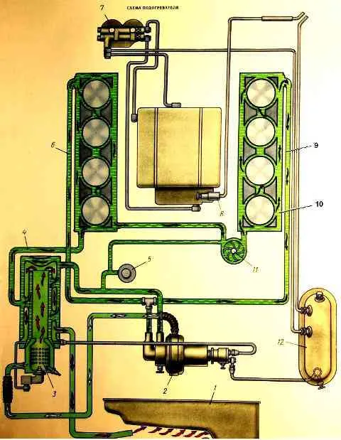
Pre-heater PZD-30 for KamAZ
The electrical equipment of the preheater is designed to perform the following functions: induction coil 2 (figure) with a transistor switch generates high voltage current
and creates a spark in spark plug 3:
- button 6 turns on the fuel heater in the power circuit; heater 5 heats the fuel entering the injector;
- solenoid fuel valve 4 turns on and off the fuel supply to the injector;
- electric motor 1 drives the pump unit.
The electric motor 1 of the pumping unit, which consumes a large current, is powered through a contactor 8. This allows the use of a low-current switch 7, which has relatively small overall dimensions.
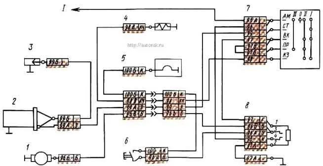
Start the heater in the following sequence: turn on the batteries to the network by pressing the remote power off button, then switch switch handle 7 to position III and press button 6.
At this point, electric motor 1 is turned on (purge mode) and power is supplied to electric fuel heater 5.
Power from the batteries is supplied to the contactor through the circuit: “+” batteries - terminals AM and BK of switch 7 - winding of contactor 8 - “-” batteries.
At the same time, contactor 8 is activated, ensuring the passage of current through the windings of electric motor 1, along the circuit:
- “+” batteries
- - terminal AM switch 7
- - closed contacts of contactor 8
- - windings of electric motor 1
- - “—” batteries.
The switched-on electric motor ensures that the heater boiler is purged with air.
Power is supplied to the electric heater 5 through the circuit: “+” of the batteries - terminal AM of the switch 7 - closed contacts of the contactor 8 - closed contacts of the button 6 - heater 5 - “-” of the batteries.
Keep button 6 pressed depending on the ambient temperature: for 30 s at -30 °C, 60 s at -40 °C and up to 90 s at -50 °C.
Then the switch handle is moved to position “I” (start mode). In this case, the electric motor 1, the electromagnetic fuel valve 4, the transistor switch 2 and the spark plug 3 will be turned on.
Valve 4 power supply circuit: “+” batteries - terminals AM and short circuit of switch 7 - valve 4 winding - “-” batteries.
Valve 4 opens and allows fuel to flow to the injector.
Power circuit of transistor switch 2:
- “+” batteries
- - terminals AM and CT of switch 7
- - switch 2
- - “—” batteries.
The switch generates a high voltage current, which is supplied to spark plug 3. Sparks are formed in the spark plug
The fuel pump forces fuel through the open valve 4 into the injector.
The atomized fuel is mixed with air entering the burner through the swirler and ignited by the spark plug.
When fuel burns, a hum is heard.
Switch handle 7 is held in position “I” for no more than 30 s.
As soon as a hum appears in the boiler, it is released and it will automatically take position “II” - the main operating mode of the heater.
In this case, electric motor 1 and valve 4, the electrical circuits of which were discussed earlier, will be turned on.
The ignition of the combustible mixture in position “II” of switch handle 7 occurs from the flame torch.
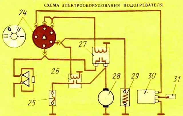
Electrical diagramof the heater
Heater
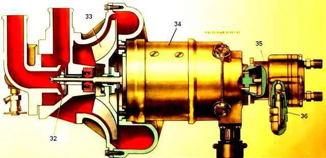
Operation diagram of the pre-heater
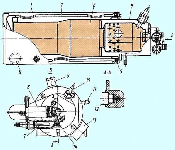
Technical characteristics of the heater
Type: PZD-30
Heating capacity, kJ/h (kcal/h): 108857(26000)
Fuel: used for the engine
Fuel consumption, kg/h: 4.5
Fuel ignition: electric spark plug from a transistor switch with a TK107 ignition coil
Candle operating time, s: 30
Fuel pre-heater: 200W electric spark plug
High-voltage spark plug: CH-423, electric spark
High voltage switch: TK 107, transistor
Solenoid valve: MKT-4
Heater electric motor: ME 252, power 180 W
Motor circuit contactor: KT 127
Fuel heater relay: 11.3704.000
Operating mode switch: VK354
Fuse: one 30 A, PRZ thermobimetallic. Protects the power supply circuits of the electrical equipment of the preheater
Seasonal maintenance of the pre-heater (service C) in the fall:
Secure the pump unit, heat exchanger, pipes, and preheater outlet pipe.
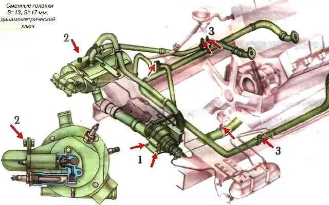
- The tightening torque of the pump unit mounting bolts is 44-53 Nm (4.5-5.4 kgf-m);
- The tightening torque of the heat exchanger mounting bolts is 44-53 Nm (4.5-5.4 kgf-m);
- The tightening torque of the M10 bolts of the pipe is 44-53 Nm (4.5-5.4 kgf-m); exhaust pipe bolts - 15-25 Nm (1.5-2.5 kgf-m).
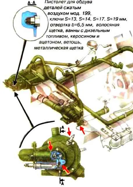
Wash the channels and filters of the solenoid valve, the fuel tank tap of the heater, the pre-heater nozzle, clean the electrodes of the pre-heater spark plugs, the combustion chamber and the heat exchanger flue, check the operation of the pre-heater, and eliminate faults (in the fall).
Before washing, disassemble the heat exchanger and remove carbon deposits.
Wash the solenoid valve filters in kerosene, the injector in acetone, and the remaining parts in diesel fuel.
Normal operation of the preheater is determined by the uniform hum of combustion in the heat exchanger and the release of exhaust gases without smoke or open flame.
If necessary, adjust the fuel flow using the fuel pump pressure reducing valve by doing the following:
- - unscrew the cap nut on the fuel pump; loosen the locknut of the adjusting screw;
- - by turning the adjusting screw to the right (fuel supply increases) or to the left (fuel supply decreases), adjust the heater operating mode.
After completing the adjustment, lock the adjusting screw with the locknut and screw on the cap nut.
To ensure normal operation of the heater, adjust the fuel supply when the ambient temperature is below zero.
After washing the car or fording in the cold season, remove water that has entered the fan air tract by turning on the pump unit for 3-4 minutes (put the switch to position III, having first disconnected the wire going to the electric fuel heater)
Possible malfunctions of the preheater and methods of elimination
Fault
- Cause of malfunction
Elimination method
Heater does not start
- There is no voltage in the heater power circuit, the polarity of the battery connection is reversed
Check fuses, electrical wires, connection polarity
- The commutator or brushes of the fan motor are faulty
Replace the electric motor or brushes
- Circulation pump motor circuit open
Check the operation of the pump by connecting it directly to the battery
No ignition, control unit turns off automatically
- Lack of fuel
Fill with fuel
- Fuel “frozen” in pipelines (at low temperature)
Fill with the recommended fuel.
Blow out the pipelines, clean the filter
- Fuel pump does not supply fuel
Check the drive, replace the pump
- Solenoid valve does not open
Check the electrical connections of the valve, replace the solenoid valve. Check the thermal fuse (press its button)
- Nozzle clogged
Replace the injector
- No ignition voltage
Check electrical wires and plug connections.
Replace the control unit.
Replace the high voltage voltage source
- Leakage of pipelines (pump sucks in air)
Tighten the fuel line connections
- Ignition electrodes are installed incorrectly
Adjust the gaps between the electrodes and the nozzle
- Too much combustion air
Adjust the air supply using the damper of the air intake pipe
The heater does not provide high-quality combustion
- Excess fuel, clogged injector
Replace the injector
Soot forms on the exhaust
- Lack of air for combustion (the heater smokes “thickly”).
Clean the suction air pipe.
Adjust the position of the air intake flap
- Poor fuel atomization
Replace the injector
Eliminate low voltage, replace brushes, replace electric motor
- Exhaust gas outlet pipe is bent or displaced, clogged with soot, dirt
Correct or clean the outlet pipe, clean the heat exchanger (flame tube and inner tube of the heat exchanger)
Blue smoke is produced
- Lack of fuel. Nozzle or filter clogged
Clean or replace the nozzle. Clean the filter.
- Too much combustion air.
Adjust the position of the air intake flap
The heater is disconnected from the thermal fuse
- Lack of coolant in the cooling system
Fill the circulation system with coolant and remove any air pockets
- The remote thermostat is faulty
Replace thermostat
- No or low coolant circulation
Check the correct connection and serviceability of the circulation pump
The heat output of the heater is insufficient
- There is soot in the combustion chamber and heat exchanger
Clean the combustion chamber and heat exchanger
- Scale has formed in the heat exchanger
Descale
The heater makes a lot of noise during operation
- The fan impeller touches the housing
Adjust the gap between the housing and the impeller and secure it
- Fuel pump is faulty
Replace the pump