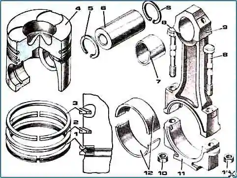
Two compression rings and one oil scraper ring are installed on the piston
Compression rings are designed to prevent gases from escaping into the crankcase during compression and expansion
In addition, they serve to transfer heat from the piston to the cylinder.
The oil scraper ring is used to remove excess oil from the working surface of the cylinder and prevent it from entering the combustion chamber.
Unscrew the four head bolts and remove the cylinder heads.

Remove the engine pan and pan gasket.

Remove the oil pump.

Unscrew the nuts of the connecting rod bolts and remove the connecting rod cover.

Since the lid fits tightly, knock it off with gentle blows of a hammer. Remove the connecting rod bearing shell from the cover.
Push the piston into the cylinder until it comes out of the cylinder, and then remove it along with the connecting rod.
Remove the connecting rod bearing shell from the connecting rod.
Remove the piston and connecting rod from the cylinder carefully so as not to damage the cylinder bore.

Check the marks on the connecting rod and connecting rod cap. If the marks are not visible, mark the connecting rod and cover with the cylinder number.
In the same way, remove the remaining pistons and connecting rods.

Use a puller to remove the piston rings.

Remove the retaining rings on both sides of the piston.
Heat the piston in an oil bath and remove the piston pin from the connecting rod, first noting the position of the connecting rod relative to the piston.
In the same way, remove the remaining pistons from the connecting rods.

After disassembly, wash all parts in gasoline.
Clean the pistons from carbon deposits. Clean the piston ring grooves with an old piston ring or a broken ring.
To reduce the clearance above the piston when assembling the engine, by selecting the piston design, ensure that it protrudes above the sealing end of the liner by 0.5-0.7 mm.

The index of the piston variant (10, 20, 30, 40) is marked on its bottom, as well as on the non-working end of the sleeve protrusion.
The free diameter of the piston ring is larger than the diameter of the cylinder, so during installation it is pressed tightly against its walls.
In the piston groove, the ring forms a labyrinth seal with a small gap.
Gas entering this labyrinth from the space above the piston, reduce their pressure and speed and press the ring against the cylinder wall.
The cut in the ring is called a lock.
In working condition, the ring should always have a gap in the lock so that it does not jam when heated.
The gap value when installing the piston into the cylinder is in the range of 0.4-0.8 mm for compression rings, 0.3-0.7 mm for oil scraper rings.

To keep the rings free one was spring-loaded; they are also installed in the grooves on the piston heightwise with a small gap.
The end gap at the upper compression ring is slightly larger than at the lower one.
Compression rings have a trapezoidal cross-section.
The working surface of the upper compression ring is coated with chrome and has a mirror surface, while the lower one is coated with molybdenum and has a matte surface.
During the movement of the piston, the rings are pressed either to the upper or to the lower planes of the grooves and thereby create the necessary seal that prevents the breakthrough of gases into the crankcase through the grooves.
At the same time, compression rings can pump oil into the combustion chamber that they remove from the cylinder walls: when the piston moves downward, the oil collects in the gap between the ring and the lower plane of the groove, and when it moves up, the oil is squeezed out into the gap between the ring and the upper plane grooves.
The vacuum in the cylinder during the intake stroke also contributes to this.
With an increase in the end clearance between the ring and the piston groove, due to the pumping action of the rings, the amount of oil pumped into the combustion chamber increases, resulting in a sharp increase in its consumption.
Therefore, it is necessary to check the end clearance after installing the rings on the piston.
Assembled oil scraper ring; it consists of a box-section cast iron ring with a chrome-plated working surface and a twisted spring expander.
Chrome plating of the rings increases their wear resistance.
The lower groove in the piston for the oil scraper ring has holes around the entire circumference to drain the oil removed by the ring from the cylinder surface.

The piston and connecting rod are connected by a hollow floating pin, the axial movement of which in the piston is limited by two spring retaining rings.
Steel connecting rods, I-section. The lower head of the connecting rod is detachable.
For precise fit of the liners, the lower head of the connecting rod is finally processed together with the cap, as a result of which the connecting rod caps are not interchangeable.
On the cover and connecting rod there are pairing marks in the form of three-digit serial numbers. In addition, the cylinder serial number is stamped on the connecting rod cover.
The sliding bearings in the upper head of the connecting rod are bimetallic one-piece bushings with a working bronze layer; in the lower head of the connecting rod there are removable interchangeable liners.
The cover of the lower head of the connecting rod is secured with nuts on two bolts pressed into the side projections of the lower head of the connecting rod
Special locking of connecting rod bolts and nuts against self-loosening is not provided.
This is explained by the fact that the connecting rod bolts are automatically protected from self-loosening due to friction in the threads, provided that the tightening requirements for the connecting rod bolt nuts are strictly met.
Conrod bolts can break due to under- or over-tightening.
The bolts must be tightened until they elongate by 0.25 - 0.27 mm.
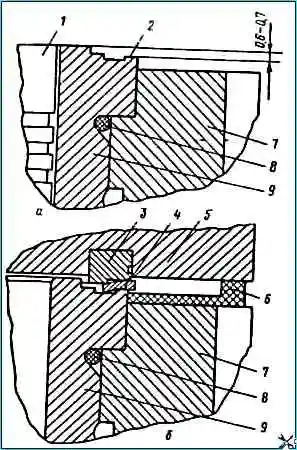
Installing cylinder liners into the block
Before installing the liners in the block, CIATIM lubricant is applied to the chamfers.
Cylinder liners are inserted carefully by hand, avoiding cutting off the sealing rings protruding from the grooves.
The piston with pin and connecting rod is assembled after heating the piston to a temperature of 80÷100˚ C.
The holes in the connecting rod under the pin and the pin itself are pre-lubricated with diesel oil.
The finger is installed using the force of the thumb. Pressing the pin using a tool is not allowed.
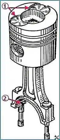
The grooves on the piston and the grooves for the whiskers of the liners on the connecting rod should be located in one direction (Fig. 16).
The piston pins are secured with retaining rings.
The piston is selected according to the distance from the generatrix of the crankpin journal of the crankshaft in its upper position to the thrust collar of the liner so that the exit of the piston bottom above the thrust collar of the cylinder liner is within 0.6÷0.7 mm, Figure 17.
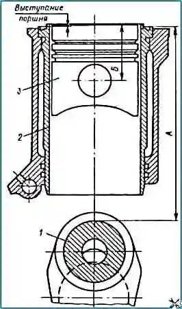
The method for measuring the distance from the generatrix of the crankpin crankpin in its upper position to the sealing collar of the cylinder liner is shown in Figure 18.
Data for selecting a piston for a liner in table 1.
Table 1
Piston index - Distance from the connecting rod journal generatrix to the thrust collar of the cylinder liner, mm - Distance from the parting plane to the center of the ring, mm:
- 10 - 260.12 – 260.24 - 75.67 – 75.71;
- 20 - 260.24 – 260.35 - 75.78 – 75.82;
- 30 - 260.35 – 260.46 - 75.89 – 75.93;
- 40 - 260.46 – 260.57 - 76.00 – 76 – 76.04
After selecting pistons at the factory, the indices of piston options 10, 20, 30, 40 are applied to the piston bottom and on the non-working protrusion of the liner end.
During assembly, you need to select pistons and cylinders with the same index.
When installing the piston into the sleeve, the recesses for the valves on the piston should be installed closer to the axis of the crankshaft.
The total gap between the ends of the lower connecting rod heads and the crankshaft journals (axial play) must be at least 0.15 mm.
Piston rings must have thermal clearances before installation on the piston. The piston ring gap is measured in a caliber with a diameter of 120+0.03 mm.
The dimensions of the gaps are indicated in the table.
Table 2
Parameters / Gap after restoration / Allowable gap:
- Lock in compression rings / 0.4–0.6 / 0.8;
- Lock in oil scraper piston rings / 0.30–0.45 / 0.7;
- End clearance of the upper compression ring / 0.12-0.17 / 0.22;
- End clearance of the lower compression ring / 0.09–0.14 / 0.19;
- Oil scraper ring end clearance / 0.07–0.11 / 0.2;
- Gap in the piston-liner interface (when measured at a distance of 0.119 – 1.162 mm from the piston bottom) / 0.12–0.16 / 0.22
Install the piston rings using a plunger expander (if available).
The oil scraper ring is inserted into the piston groove and the ring is put on so that the joint of the expander is at an angle of 180˚ to the ring lock.
After this, install the compression rings. First we insert the ring coated with molybdenum, then the ring coated with chrome.
The locks of adjacent rings move in different directions.
")

")
")
")
")
")
")
")